Dell Force10 S25N-S50N Installing S25N and S25V Systems - Page 31
Installing Backup Power, Backup Power Components
 |
View all Dell Force10 S25N-S50N manuals
Add to My Manuals
Save this manual to your list of manuals |
Page 31 highlights
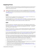
Chapter 4 Installing Backup Power This chapter covers the following topics: • Backup Power Components • The Power Connections on the Switch on page 32 • Installing the Redundant DC Power Supply for the S25V on page 33 • Inserting Tandem PSUs into a Rack on page 34 • Connecting the DC-to-DC Cable on page 34 The S25N has two AC connections, with no external backup option. You can connect either one or both. When both are connected, they operate in load-sharing mode. The S25V has both AC and DC power connections. You can connect either one or both. When both are connected, they operate in load-sharing mode, but the AC input is slightly preferred over the DC (60/40). If you connect the 470W DC Force10 Redundant Power Supply Unit (PSU) to the Current Sharing lug on the switch, the power supplies operates in current-sharing mode, which means they operate both in load-sharing mode and in additive mode, yielding a total of 940W (790W for PoE). Note: Neither internal nor external S-Series power supplies are field serviceable. If an internal power supply fails, the switch must be replaced. Danger: To prevent electrical shock, make sure the switch is grounded properly. If you do not ground your equipment correctly, excessive emissions can result. Use a qualified electrician to ensure that the power cables meet your local electrical requirements. See other relevant cautions in Information Symbols and Warnings on page 5. Backup Power Components The optional Redundant Power Supply Unit (PSU) for the S25V supplies 470W DC, supporting both the switch itself and the PoE feature. The PSU kit includes: • The AC/DC rectifier (catalog name S50-01-PSU-V) • DC-to-DC cable to connect the PSU to the switch • AC cable to connect the PSU to the AC power source • PSU mounting hardware: extended rack ears, twinning plate, screws, cage nuts, and four rubber feet that you can attach to the PSU if you want to set it on a table Installing S25N and S25V Systems 31
-
 1
1 -
2
-
3
-
4
-
5
-
6
-
7
-
8
-
9
-
10
-
11
-
12
-
13
-
14
-
15
-
16
-
17
-
18
-
19
-
20
-
21
-
22
-
23
-
24
-
25
-
 26
26 -
 27
27 -
 28
28 -
 29
29 -
 30
30 -
 31
31 -
 32
32 -
 33
33 -
 34
34 -
 35
35 -
 36
36 -
37
-
38
-
39
-
40
-
41
-
42
-
43
-
44
-
45
-
46
-
47
-
48
-
49
-
50
-
51
-
52
-
53
-
54
 |
 |
