Dell Force10 S25N-S50N Installing S25N and S25V Systems - Page 28
Connecting Two Switches,
 |
View all Dell Force10 S25N-S50N manuals
Add to My Manuals
Save this manual to your list of manuals |
Page 28 highlights
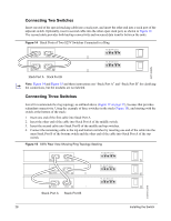
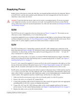
Connecting Two Switches Insert one end of the special stacking cable into a stack port, and insert the other end into a stack port of the adjacent switch. Optionally, insert a second cable into the other open stack port, as shown in Figure 14. The second cable provides both backup connectivity and increased data transfer between the units. Figure 14 Stack Ports of Two S25V Switches Connected in a Ring STACK STACK STACK STACK FG -48V -48V Current RTN Sharing FG -48V -48V Current RTN Sharing fn00151s25V Stack Port A Stack Port B Note: Figure 14 and Figure 15 and these instructions use "Stack Port A" and "Stack Port B" for clarifying the connections, but the modules are not labeled. Connecting Three Switches Force10 recommends the ring topology, as outlined above (Figure 12 on page 27), because that provides redundant connectivity. Using the example of three switches in the stack (Figure 15), and starting with the switch at the bottom of the stack: 1 Insert one end of the first cable into Stack Port A. 2. Insert the other end of the cable into Stack Port A of the middle switch. 3. Insert the second cable into Stack Port B of the middle and top switches. 4. Connect the remaining cable to the top and bottom switches by inserting one end of the cable into the open Stack Port B of the bottom switch and the other end of the cable into Stack Port A of the top switch. Figure 15 S25V Rear View Showing Ring Topology Stacking STACK STACK STACK STACK STACK Stack Port A STACK Stack Port B FG -48V -48V Current RTN Sharing FG -48V -48V Current RTN Sharing FG -48V -48V Current RTN Sharing fn00152s50V1 28 Installing the Switch
-
 1
1 -
2
-
3
-
4
-
5
-
6
-
7
-
8
-
9
-
10
-
11
-
12
-
13
-
14
-
15
-
16
-
17
-
18
-
19
-
20
-
21
-
22
-
 23
23 -
 24
24 -
 25
25 -
 26
26 -
 27
27 -
 28
28 -
 29
29 -
 30
30 -
 31
31 -
 32
32 -
 33
33 -
34
-
35
-
36
-
37
-
38
-
39
-
40
-
41
-
42
-
43
-
44
-
45
-
46
-
47
-
48
-
49
-
50
-
51
-
52
-
53
-
54
 |
 |
