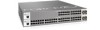
Dell Force10 S25N-S50N Installing S25N and S25V Systems - Page 5
About this Guide, Information Symbols and Warnings, Preface
 |
View all Dell Force10 S25N-S50N manuals
Add to My Manuals
Save this manual to your list of manuals |
Page 5 highlights
Preface About this Guide This guide provides site preparation recommendations, step-by-step procedures for rack mounting and desk mounting, inserting optional modules, and connecting to a power source. After you have completed the hardware installation and power-up of the system, refer to the FTOS Configuration Guide for the S-Series for software configuration information and the FTOS Command Reference for the S-Series for detailed Command Line Interface (CLI) information, as detailed in Related Publications, below. Information Symbols and Warnings The following graphic symbols are used in this document to bring attention to hazards that exist when handling the system and its components. Please read these alerts and heed their warnings and cautions. Table 1 describes symbols contained in this guide. Table 1 Information Symbols Symbol Warning Description Danger This symbol warns that improper handling and installation could result in bodily injury. Before you begin work on this equipment, be aware of hazards involving electrical circuitry, networking environments, and instigate accident prevention procedures. Caution This symbol informs you that improper handling and installation could result in equipment damage or loss of data. Warning This symbol informs you that improper handling may reduce your component or system performance. Note This symbol informs you of important operational information. Danger: The installation of this equipment shall be performed by trained and qualified personnel only. Read this guide before installing and powering up this equipment. This equipment contains two power cords. Disconnect both power cords before servicing. Installing S25N and S25V Systems 5
-
 1
1 -
 2
2 -
 3
3 -
 4
4 -
 5
5 -
 6
6 -
 7
7 -
 8
8 -
 9
9 -
 10
10 -
 11
11 -
12
-
13
-
14
-
15
-
16
-
17
-
18
-
19
-
20
-
21
-
22
-
23
-
24
-
25
-
26
-
27
-
28
-
29
-
30
-
31
-
32
-
33
-
34
-
35
-
36
-
37
-
38
-
39
-
40
-
41
-
42
-
43
-
44
-
45
-
46
-
47
-
48
-
49
-
50
-
51
-
52
-
53
-
54
 |
 |
