Dell Force10 S25N-S50N Installing S25N and S25V Systems - Page 39
Installing Optics
 |
View all Dell Force10 S25N-S50N manuals
Add to My Manuals
Save this manual to your list of manuals |
Page 39 highlights
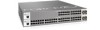
Installing Optics The S25N and S25V each have four receptacles at the right end of their faceplates that accommodate 10/100/1000 SFP optical transceivers. On the back of the switches, there are two bays that accept either stacking modules or 10GbE modules (CX4 or XFP). A 10GbE module contains two ports. 10GbE modules should only be inserted or removed when the switch is powered down, as detailed in Inserting Optional Modules (10-Gigabit or Stacking) on page 19 in Chapter 3, Installing the Switch. SFP and XFP transceivers can be inserted or removed while the switch is running. Caution: Before connecting a transceiver to a source, check the receive power of the transceiver with an optical power meter. Generally, Force10 specified optics are not to be subjected to receive power higher than that stipulated by the optic specification. If the optic is exposed to optical power in excess of the specification, there is a high likelihood that it will be damaged. Optical specifications for Force10 branded devices are at the following URL: http://www.force10networks.com/products/mediaspecifications.asp Force10 Networks offers various types of SFP and XFP transceivers. For details, see: http://www.force10networks.com/products/specifications.asp Installing SFPs To install an SFP into one of the four ports at the right front of the switch, follow the steps below: Warning: Electrostatic discharge (ESD) damage can occur if components are mishandled. Always wear an ESD-preventive wrist or heel ground strap when handling the system and its components. Step 1 2 Task Position the SFP so it is in the upright position. (The SFP has a key that prevents it from being inserted incorrectly.) Insert the SFP into the port until it gently snaps into place. Figure 26 Front View of S25N with SFP fn00162s25N Installing S25N and S25V Systems 39
-
 1
1 -
2
-
3
-
4
-
5
-
6
-
7
-
8
-
9
-
10
-
11
-
12
-
13
-
14
-
15
-
16
-
17
-
18
-
19
-
20
-
21
-
22
-
23
-
24
-
25
-
26
-
27
-
28
-
29
-
30
-
31
-
32
-
33
-
 34
34 -
 35
35 -
 36
36 -
 37
37 -
 38
38 -
 39
39 -
 40
40 -
 41
41 -
 42
42 -
 43
43 -
 44
44 -
45
-
46
-
47
-
48
-
49
-
50
-
51
-
52
-
53
-
54
 |
 |
