Dell Latitude 3190 Owners Manual - Page 35
System board, Removing system board
 |
View all Dell Latitude 3190 manuals
Add to My Manuals
Save this manual to your list of manuals |
Page 35 highlights
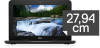
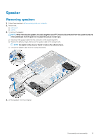
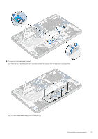
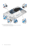
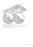
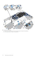
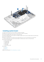
3. Affix the adhesive tape to secure the touchpad bracket to the touchpad. 4. Connect the touchpad cable to the connector and affix the adhesive-backed cable to secure it to the touchpad. 5. Install the: a) speaker b) battery c) base cover 6. Follow the procedure in After working inside your computer. System board Removing system board 1. Follow the procedure in Before working inside your computer. NOTE: For Latitude 3190, the system board is secured to the palm rest with five M2x3 screws. Technicians should take note that the four M2x3 screws that secure the thermal plate to the system board do not have to be removed to remove the system board from the system NOTE: The latitude 3190 does not have a heat sink and fan assembly. However, the CPU is covered by a thermal plate and aluminum shielding which should not be disassembled from the system board. 2. Remove the: a) base cover b) battery c) SSD card 3. Disconnect the following cables: a) coin cell battery cable [1] b) Audio cable [2] c) speaker cable [3] d) keyboard cable [4] e) touch pad cable [5] f) power connector cable [6] Disassembly and reassembly 35
-
 1
1 -
2
-
3
-
4
-
5
-
6
-
7
-
8
-
9
-
10
-
11
-
12
-
13
-
14
-
15
-
16
-
17
-
18
-
19
-
20
-
21
-
22
-
23
-
24
-
25
-
26
-
27
-
28
-
29
-
 30
30 -
 31
31 -
 32
32 -
 33
33 -
 34
34 -
 35
35 -
 36
36 -
 37
37 -
 38
38 -
 39
39 -
 40
40 -
41
-
42
-
43
-
44
-
45
-
46
-
47
-
48
-
49
-
50
-
51
-
52
-
53
-
54
-
55
-
56
-
57
-
58
-
59
-
60
-
61
-
62
-
63
-
64
-
65
 |
 |