Dell Latitude 3190 Owners Manual - Page 42
Installing display assembly, Display bezel, Removing display bezel
 |
View all Dell Latitude 3190 manuals
Add to My Manuals
Save this manual to your list of manuals |
Page 42 highlights
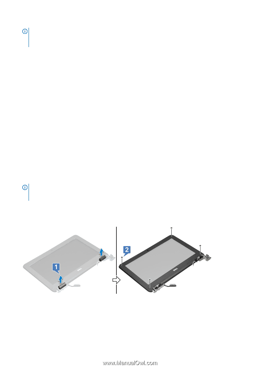
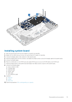
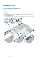
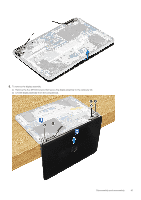
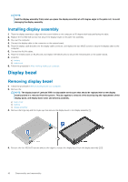
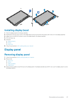
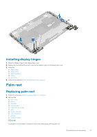
NOTE: Hold the display assembly firmly when you place the display assembly at a 90 degree angle to the palm rest, to avoid damaging the display assembly Installing display assembly 1. Place the display assembly to align with the screw holders on the computer at 90 degree with keyboard facing the table. 2. Replace the five M2.5x5 screws that secure the display hinges to the palm-rest assembly. 3. Flip over the computer. 4. Connect the display cable to the connector on the system board. 5. Place the display cable bracket over the display cable connector, and replace the two M2x3 screws to secure the display cable to the computer. 6. Connect the WLAN cables. 7. Place the metal bracket on WLAN card, and replace the M2x3 screw to secure the metal bracket on the system board. 8. Install the: a) battery b) base cover 9. Follow the procedure in After working inside your computer. Display bezel Removing display bezel 1. Follow the procedure in Before working inside your computer. 2. Remove the: NOTE: The display bezel of Latitude 3190 is a disposable service part that should be replaced with a new display bezel anytime it is removed from the system. This also applies to removal of the bezel during the replacement of the display panel, and display back-cover and antenna assembly. a) base cover b) battery c) display assembly 3. Remove the hinge cap and the mylar cap that secures the display bezel to the display assembly [1]. 4. Remove the four M2.5x3.5 screws and pry the edges to release the display bezel from the display assembly [2,3]. 42 Disassembly and reassembly
-
 1
1 -
2
-
3
-
4
-
5
-
6
-
7
-
8
-
9
-
10
-
11
-
12
-
13
-
14
-
15
-
16
-
17
-
18
-
19
-
20
-
21
-
22
-
23
-
24
-
25
-
26
-
27
-
28
-
29
-
30
-
31
-
32
-
33
-
34
-
35
-
36
-
 37
37 -
 38
38 -
 39
39 -
 40
40 -
 41
41 -
 42
42 -
 43
43 -
 44
44 -
 45
45 -
 46
46 -
 47
47 -
48
-
49
-
50
-
51
-
52
-
53
-
54
-
55
-
56
-
57
-
58
-
59
-
60
-
61
-
62
-
63
-
64
-
65
 |
 |