Dell Latitude 3190 Owners Manual - Page 45
Camera, Removing camera
 |
View all Dell Latitude 3190 manuals
Add to My Manuals
Save this manual to your list of manuals |
Page 45 highlights
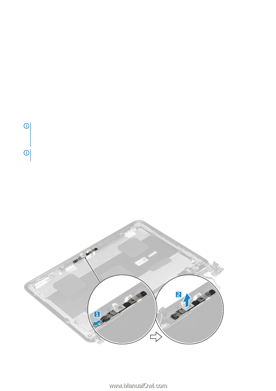
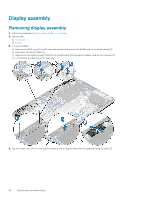
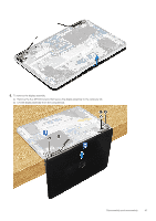
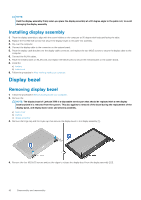
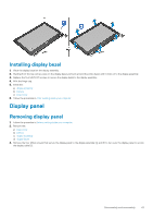
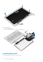
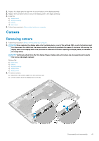
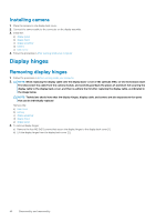
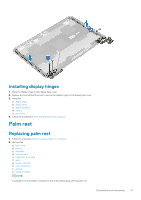
2. Replace the display panel to align with the screw holders on the display assembly. 3. Replace the four M2x3 screws to secure the display panel to the display assembly. 4. Install the: a) display bezel b) display assembly c) battery d) base cover 5. Follow the procedure in After working inside your computer Camera Removing camera 1. Follow the procedure in Before working inside your computer. 2. NOTE: When replacing the display cable onto the display back- cover of the Latitude 3190, on-site technicians must first disconnect the cable from the camera module, and carefully peel back the pieces of aluminum foil securing the display cable to the display back-cover, and then re-adhere the foil after replacing the display cable, as indicated in the image below. NOTE: Technicians should note that the display hinges, display cable, and camera are also separate service parts that can be individually replaced Remove the: a) base cover b) battery c) display assembly d) display bezel e) display panel 3. To remove camera: a) Disconnect the camera cable from the connector [1]. b) Lift the camera from the display back cover [2]. Disassembly and reassembly 45
-
 1
1 -
2
-
3
-
4
-
5
-
6
-
7
-
8
-
9
-
10
-
11
-
12
-
13
-
14
-
15
-
16
-
17
-
18
-
19
-
20
-
21
-
22
-
23
-
24
-
25
-
26
-
27
-
28
-
29
-
30
-
31
-
32
-
33
-
34
-
35
-
36
-
37
-
38
-
39
-
 40
40 -
 41
41 -
 42
42 -
 43
43 -
 44
44 -
 45
45 -
 46
46 -
 47
47 -
 48
48 -
 49
49 -
 50
50 -
51
-
52
-
53
-
54
-
55
-
56
-
57
-
58
-
59
-
60
-
61
-
62
-
63
-
64
-
65
 |
 |