Dell Latitude CPi Service Manual - Page 39
included in the illustration. Match the actual screw to the graphic in the illustra
 |
View all Dell Latitude CPi manuals
Add to My Manuals
Save this manual to your list of manuals |
Page 39 highlights
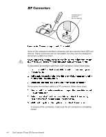
Slide the battery bay latch away from the center of the computer. Then slide the battery out of the battery bay (see Figure 4-2). battery bay latch battery The illustrations in the following removal procedures provide the correct screw length as part of the screw's label. A graphic for that length screw is also included in the illustration. Match the actual screw to the graphic in the illustration to check for correct length. Removing and Replacing Parts 4-3
-
 1
1 -
2
-
3
-
4
-
5
-
6
-
7
-
8
-
9
-
10
-
11
-
12
-
13
-
14
-
15
-
16
-
17
-
18
-
19
-
20
-
21
-
22
-
23
-
24
-
25
-
26
-
27
-
28
-
29
-
30
-
31
-
32
-
33
-
 34
34 -
 35
35 -
 36
36 -
 37
37 -
 38
38 -
 39
39 -
 40
40 -
 41
41 -
 42
42 -
 43
43 -
 44
44 -
45
-
46
-
47
-
48
-
49
-
50
-
51
-
52
-
53
-
54
-
55
-
56
-
57
-
58
-
59
-
60
-
61
-
62
-
63
-
64
-
65
-
66
-
67
-
68
-
69
-
70
-
71
-
72
-
73
-
74
-
75
-
76
-
77
-
78
-
79
-
80
-
81
-
82
-
83
-
84
-
85
-
86
-
87
-
88
-
89
-
90
-
91
-
92
-
93
 |
 |

Removing and Replacing Parts
4-3
Slide the battery bay latch away from the center of the computer. Then
slide the battery out of the battery bay (see Figure 4-2).
6FUHZ±,GHQWLILFDWLRQ±DQG±7LJKWHQLQJ
The illustrations in the following removal procedures provide the correct screw
length as part of the screw’s label. A graphic for that length screw is also
included in the illustration. Match the actual screw to the graphic in the illustra-
tion to check for correct length.
battery bay latch
battery