Dell Latitude CPi Service Manual - Page 71
the board prior to securing the board in the display-assembly top cover. After
 |
View all Dell Latitude CPi manuals
Add to My Manuals
Save this manual to your list of manuals |
Page 71 highlights
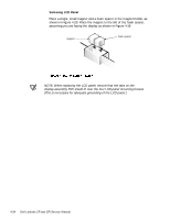
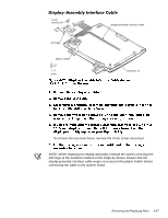
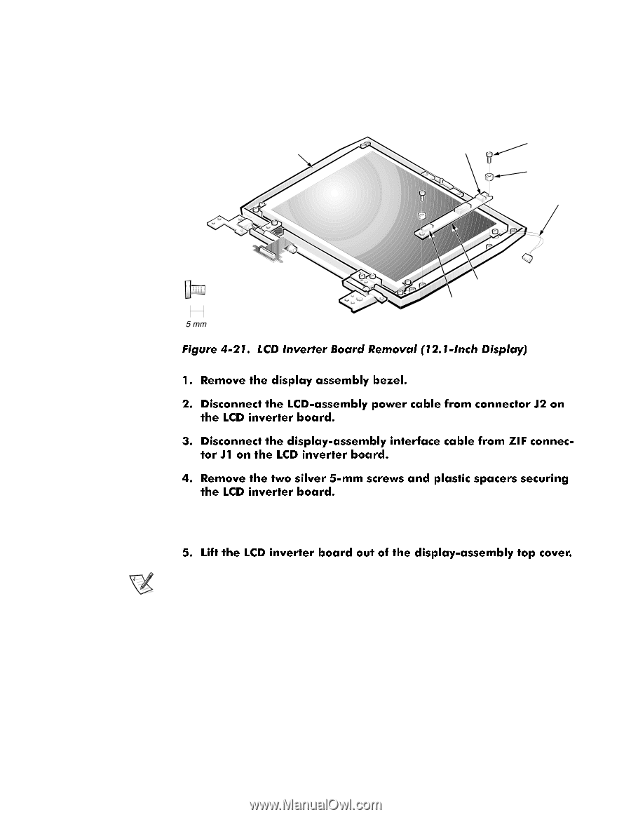
The following subsections describe how to remove an LCD inverter board from a 12.1-inch or 13.3-inch LCD display. display-assembly top cover connector J2 5-mm screws (2) spacer (2) LCD-assembly power cable LCD inverter board connector J1 Note the placement of the EMI shield over the lower screw boss, and the routing of the LCD-panel power cable around the upper screw boss. NOTE: When installing the inverter board, connect the LCD interface cable to the board prior to securing the board in the display-assembly top cover. After installing the inverter board, ensure that the LCD-panel power cable is routed around the plastic screw bosses in the display-assembly top cover. Removing and Replacing Parts 4-35
-
 1
1 -
2
-
3
-
4
-
5
-
6
-
7
-
8
-
9
-
10
-
11
-
12
-
13
-
14
-
15
-
16
-
17
-
18
-
19
-
20
-
21
-
22
-
23
-
24
-
25
-
26
-
27
-
28
-
29
-
30
-
31
-
32
-
33
-
34
-
35
-
36
-
37
-
38
-
39
-
40
-
41
-
42
-
43
-
44
-
45
-
46
-
47
-
48
-
49
-
50
-
51
-
52
-
53
-
54
-
55
-
56
-
57
-
58
-
59
-
60
-
61
-
62
-
63
-
64
-
65
-
 66
66 -
 67
67 -
 68
68 -
 69
69 -
 70
70 -
 71
71 -
 72
72 -
 73
73 -
 74
74 -
 75
75 -
 76
76 -
77
-
78
-
79
-
80
-
81
-
82
-
83
-
84
-
85
-
86
-
87
-
88
-
89
-
90
-
91
-
92
-
93
 |
 |
Removing and Replacing Parts
4-35
/&’±,QYHUWHU±%RDUG
The following subsections describe how to remove an LCD inverter board from
a 12.1-inch or 13.3-inch LCD display.
²³´²µ,QFK±/&’±’LVSOD\
Note the placement of the EMI shield over the lower screw boss, and the
routing of the LCD-panel power cable around the upper screw boss.
NOTE: When installing the inverter board, connect the LCD interface cable to
the board prior to securing the board in the display-assembly top cover. After
installing the inverter board, ensure that the LCD-panel power cable is routed
around the plastic screw bosses in the display-assembly top cover.
LCD inverter board
display-assembly top cover
connector J1
connector J2
5-mm
screws (2)
spacer (2)
LCD-assembly
power cable