vi
Hard-Disk Drive Assembly. . . . . . . . . . . . . . . . . . . . . . . . . . . . . . . . . . 4-15
Memory Module Cover . . . . . . . . . . . . . . . . . . . . . . . . . . . . . . . . . . . . 4-16
Memory Modules . . . . . . . . . . . . . . . . . . . . . . . . . . . . . . . . . . . . . . . . 4-17
Keyboard Assembly. . . . . . . . . . . . . . . . . . . . . . . . . . . . . . . . . . . . . . . 4-18
Back Cover Assembly . . . . . . . . . . . . . . . . . . . . . . . . . . . . . . . . . . . . . 4-20
Palmrest Assembly . . . . . . . . . . . . . . . . . . . . . . . . . . . . . . . . . . . . . . . 4-21
Touch-Pad Interface Module . . . . . . . . . . . . . . . . . . . . . . . . . . . . . . . . 4-23
Power Button. . . . . . . . . . . . . . . . . . . . . . . . . . . . . . . . . . . . . . . . . . . . 4-24
Display Assembly Components. . . . . . . . . . . . . . . . . . . . . . . . . . . . . . 4-25
Display Assembly . . . . . . . . . . . . . . . . . . . . . . . . . . . . . . . . . . . . . . . . 4-27
Display Assembly Bezel. . . . . . . . . . . . . . . . . . . . . . . . . . . . . . . . . . . . 4-29
Display Assembly Latch. . . . . . . . . . . . . . . . . . . . . . . . . . . . . . . . . . . . 4-30
LCD Panel
. . . . . . . . . . . . . . . . . . . . . . . . . . . . . . . . . . . . . . . . . . . . . 4-31
12.1-Inch LCD Displays . . . . . . . . . . . . . . . . . . . . . . . . . . . . . . . . . 4-31
13.3-Inch LCD Displays . . . . . . . . . . . . . . . . . . . . . . . . . . . . . . . . . 4-32
LCD Inverter Board . . . . . . . . . . . . . . . . . . . . . . . . . . . . . . . . . . . . . . . 4-35
12.1-Inch LCD Display . . . . . . . . . . . . . . . . . . . . . . . . . . . . . . . . . . 4-35
13.3-Inch LCD Display . . . . . . . . . . . . . . . . . . . . . . . . . . . . . . . . . . 4-36
Display-Assembly Interface Cable . . . . . . . . . . . . . . . . . . . . . . . . . . . . 4-37
LCD Display Hinge. . . . . . . . . . . . . . . . . . . . . . . . . . . . . . . . . . . . . . . . 4-38
Display-Assembly Top Cover
. . . . . . . . . . . . . . . . . . . . . . . . . . . . . . . 4-39
Bottom Case Assembly. . . . . . . . . . . . . . . . . . . . . . . . . . . . . . . . . . . . 4-40
Modular Bay Devices (Diskette Drive,
CD-ROM Drive, Battery, or Travel Module)
. . . . . . . . . . . . . . . . . . . . 4-42
Audio Shield
. . . . . . . . . . . . . . . . . . . . . . . . . . . . . . . . . . . . . . . . . . . . 4-43
Audio Board
. . . . . . . . . . . . . . . . . . . . . . . . . . . . . . . . . . . . . . . . . . . . 4-44
Bottom Case Bracket. . . . . . . . . . . . . . . . . . . . . . . . . . . . . . . . . . . . . . 4-45
Module Latch Assemblies . . . . . . . . . . . . . . . . . . . . . . . . . . . . . . . . . . 4-46
Speakers . . . . . . . . . . . . . . . . . . . . . . . . . . . . . . . . . . . . . . . . . . . . . . . 4-47
System Board Assembly . . . . . . . . . . . . . . . . . . . . . . . . . . . . . . . . . . . 4-48
Exhaust Fan
. . . . . . . . . . . . . . . . . . . . . . . . . . . . . . . . . . . . . . . . . . . . 4-50
I/R Board . . . . . . . . . . . . . . . . . . . . . . . . . . . . . . . . . . . . . . . . . . . . . . . 4-51
Reserve Battery
. . . . . . . . . . . . . . . . . . . . . . . . . . . . . . . . . . . . . . . . . 4-52
,QGH[
)LJXUHV
Figure 1-1.
Front View of the Computer
. . . . . . . . . . . . . . . . . . . . . . . . . 1-2
Figure 1-2.
Back View of the Computer . . . . . . . . . . . . . . . . . . . . . . . . . . 1-3
Figure 1-3.
Bottom View of the Computer . . . . . . . . . . . . . . . . . . . . . . . . 1-3
Figure 1-4.
Indicator Panel
. . . . . . . . . . . . . . . . . . . . . . . . . . . . . . . . . . . . 1-4
Figure 3-1.
Battery Indicator . . . . . . . . . . . . . . . . . . . . . . . . . . . . . . . . . . . 3-4
Figure 4-1.
Computer Orientation . . . . . . . . . . . . . . . . . . . . . . . . . . . . . . . 4-1
Figure 4-2.
Main Battery Assembly Removal . . . . . . . . . . . . . . . . . . . . . . 4-3
 1
1 2
2 3
3 4
4 5
5 6
6 7
7 8
8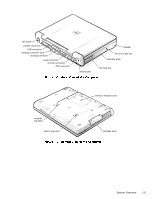 9
9 10
10