Dell Latitude CPi Service Manual - Page 65
If removing the bezel from a 12.1-inch display, If removing the bezel from a 13.3-inch display
 |
View all Dell Latitude CPi manuals
Add to My Manuals
Save this manual to your list of manuals |
Page 65 highlights
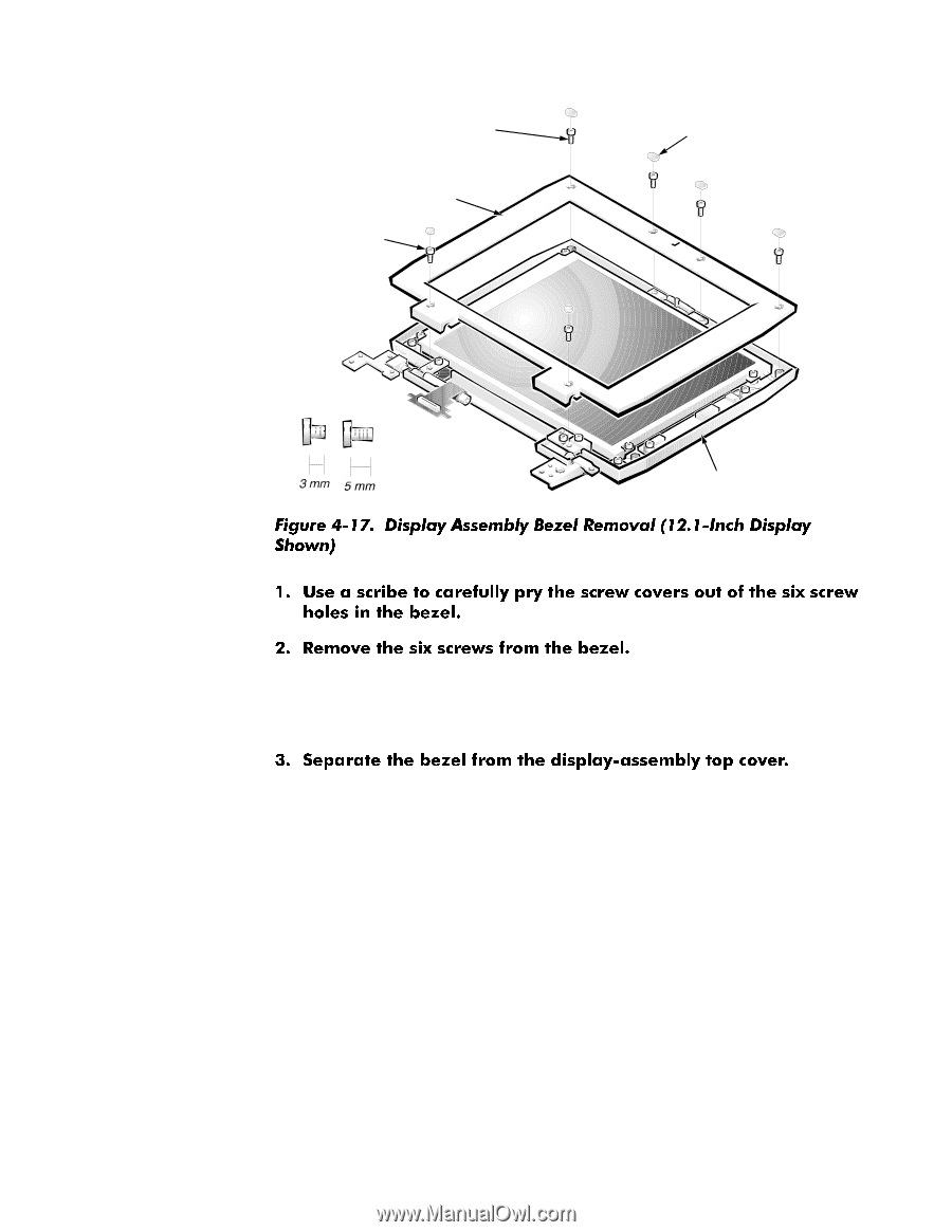
l 5-mm screws (4) (12.1-inch displays); 3-mm screws (4) (13.3-inch displays) display assembly bezel 5-mm screws (2) screw covers (6) display-assembly top cover On 12.1-inch displays, all six screws are 5-mm screws. On 13.3-inch displays, the four upper screws are 3-mm screws, while the lower two screws are 5-mm in length. If removing the bezel from a 12.1-inch display - The bezel is secured by snaps around all four of its edges. Insert your fingertips between the bezel and the LCD panel, and lift upward on the bezel to release the hidden snaps. Avoid pressing on the surface of the LCD panel. If removing the bezel from a 13.3-inch display - The bezel is secured by snaps along its lower edge, and hooks along its right and left edges. a. Insert your fingertips between the lower edge of the bezel and the LCD panel, and lift upward on the bezel to release the hidden snaps. b. Lift the lower right corner of the bezel slightly, and then slide the bezel off of the display assembly until the hooks on the right and left edges release from the display-assembly top cover. Removing and Replacing Parts 4-29
-
 1
1 -
2
-
3
-
4
-
5
-
6
-
7
-
8
-
9
-
10
-
11
-
12
-
13
-
14
-
15
-
16
-
17
-
18
-
19
-
20
-
21
-
22
-
23
-
24
-
25
-
26
-
27
-
28
-
29
-
30
-
31
-
32
-
33
-
34
-
35
-
36
-
37
-
38
-
39
-
40
-
41
-
42
-
43
-
44
-
45
-
46
-
47
-
48
-
49
-
50
-
51
-
52
-
53
-
54
-
55
-
56
-
57
-
58
-
59
-
 60
60 -
 61
61 -
 62
62 -
 63
63 -
 64
64 -
 65
65 -
 66
66 -
 67
67 -
 68
68 -
 69
69 -
 70
70 -
71
-
72
-
73
-
74
-
75
-
76
-
77
-
78
-
79
-
80
-
81
-
82
-
83
-
84
-
85
-
86
-
87
-
88
-
89
-
90
-
91
-
92
-
93
 |
 |