Dell Latitude CPi Service Manual - Page 82
Ensure that the plunger is inserted in its respective hole, that the side
 |
View all Dell Latitude CPi manuals
Add to My Manuals
Save this manual to your list of manuals |
Page 82 highlights
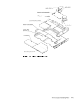
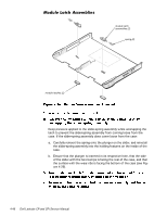
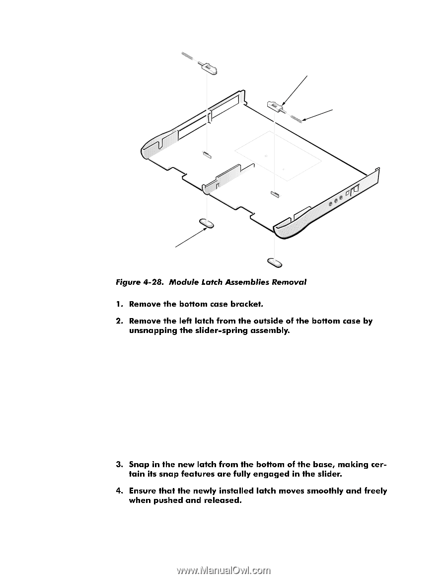
module latch assemblies (2) spring (2) module latches (2) Keep pressure applied to the slider-spring assembly while unsnapping the latch to prevent the slider-spring assembly from coming loose from the case. If the slider-spring assembly does come loose from the case: a. Carefully reinsert the spring onto the plunger on the slider, and reinstall the slider-spring assembly into the holding features on the inside of the case. b. Ensure that the plunger is inserted in its respective hole, that the side of the slider with the two bumps is facing the rear of the case, and that the surface with the wear ribs is facing the bottom of the case (see Figure 4-29). 4-46 Dell Latitude CP and CPi Service Manual
-
 1
1 -
2
-
3
-
4
-
5
-
6
-
7
-
8
-
9
-
10
-
11
-
12
-
13
-
14
-
15
-
16
-
17
-
18
-
19
-
20
-
21
-
22
-
23
-
24
-
25
-
26
-
27
-
28
-
29
-
30
-
31
-
32
-
33
-
34
-
35
-
36
-
37
-
38
-
39
-
40
-
41
-
42
-
43
-
44
-
45
-
46
-
47
-
48
-
49
-
50
-
51
-
52
-
53
-
54
-
55
-
56
-
57
-
58
-
59
-
60
-
61
-
62
-
63
-
64
-
65
-
66
-
67
-
68
-
69
-
70
-
71
-
72
-
73
-
74
-
75
-
76
-
 77
77 -
 78
78 -
 79
79 -
 80
80 -
 81
81 -
 82
82 -
 83
83 -
 84
84 -
 85
85 -
 86
86 -
 87
87 -
88
-
89
-
90
-
91
-
92
-
93
 |
 |
4-46
Dell Latitude CP and CPi Service Manual
0RGXOH±/DWFK±$VVHPEOLHV
Keep pressure applied to the slider-spring assembly while unsnapping the
latch to prevent the slider-spring assembly from coming loose from the
case. If the slider-spring assembly does come loose from the case:
a.
Carefully reinsert the spring onto the plunger on the slider, and reinstall
the slider-spring assembly into the holding features on the inside of the
case.
b.
Ensure that the plunger is inserted in its respective hole, that the side
of the slider with the two bumps is facing the rear of the case, and that
the surface with the wear ribs is facing the bottom of the case (see Fig-
ure 4-29).
module latch
assemblies (2)
spring (2)
module latches (2)