Dell Latitude CPi Service Manual - Page 74
Dell Latitude CPi Manual
 |
View all Dell Latitude CPi manuals
Add to My Manuals
Save this manual to your list of manuals |
Page 74 highlights
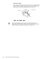
NOTES: To aid in reinstalling the hinges and display assembly, the right and left hinges are marked by an "R" and an "L," respectively. Install the four screws securing the hinges at the locations marked by arrows on the face of each hinge. The right bracket on a 12.1-inch display fits above the right hinge (see Figure 4-14). 4-38 Dell Latitude CP and CPi Service Manual
-
 1
1 -
2
-
3
-
4
-
5
-
6
-
7
-
8
-
9
-
10
-
11
-
12
-
13
-
14
-
15
-
16
-
17
-
18
-
19
-
20
-
21
-
22
-
23
-
24
-
25
-
26
-
27
-
28
-
29
-
30
-
31
-
32
-
33
-
34
-
35
-
36
-
37
-
38
-
39
-
40
-
41
-
42
-
43
-
44
-
45
-
46
-
47
-
48
-
49
-
50
-
51
-
52
-
53
-
54
-
55
-
56
-
57
-
58
-
59
-
60
-
61
-
62
-
63
-
64
-
65
-
66
-
67
-
68
-
 69
69 -
 70
70 -
 71
71 -
 72
72 -
 73
73 -
 74
74 -
 75
75 -
 76
76 -
 77
77 -
 78
78 -
 79
79 -
80
-
81
-
82
-
83
-
84
-
85
-
86
-
87
-
88
-
89
-
90
-
91
-
92
-
93
 |
 |
4-38
Dell Latitude CP and CPi Service Manual
/&’±’LVSOD\±+LQJH±±±
NOTES: To aid in reinstalling the hinges and display assembly, the right and left
hinges are marked by an “R” and an “L,” respectively. Install the four screws
securing the hinges at the locations marked by arrows on the face of each
hinge.
The right bracket on a 12.1-inch display fits above the right hinge (see
Figure 4-14).