Dell OptiPlex 3011 AIO Owner's Manual - Page 31
Installing the System Board, Removing the Display Bracket - hard drive removal
 |
View all Dell OptiPlex 3011 AIO manuals
Add to My Manuals
Save this manual to your list of manuals |
Page 31 highlights
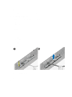
Installing the System Board 1. Place the system board on the computer. 2. Tighten the screws to secure the system board to the base panel. 3. Connect all the cables to the system board. 4. Install: a) optical disk drive b) hard drive c) heat sink d) WLAN card e) memory f) system board cover g) back cover h) VESA stand i) stand cover 5. Follow the procedures in After Working Inside Your Computer. Removing the Display Bracket 1. Follow the procedures in Before Working Inside Your Computer. 2. Remove: a) stand cover b) VESA stand c) back cover d) system board cover e) WLAN card f) memory g) heat sink h) hard drive i) optical disk drive j) control board k) system fan l) intrusion switch m) power switch n) system board 3. Release the camera cable and the display cable from their tabs on the display bracket. 31
-
 1
1 -
2
-
3
-
4
-
5
-
6
-
7
-
8
-
9
-
10
-
11
-
12
-
13
-
14
-
15
-
16
-
17
-
18
-
19
-
20
-
21
-
22
-
23
-
24
-
25
-
 26
26 -
 27
27 -
 28
28 -
 29
29 -
 30
30 -
 31
31 -
 32
32 -
 33
33 -
 34
34 -
 35
35 -
 36
36 -
37
-
38
-
39
-
40
-
41
-
42
-
43
-
44
-
45
-
46
-
47
-
48
-
49
-
50
-
51
-
52
-
53
-
54
-
55
-
56
-
57
-
58
-
59
-
60
-
61
-
62
-
63
 |
 |
