Dell OptiPlex GXi Reference and Installation Guide ( - Page 59
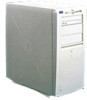
Inside Your Computer, Replacing the Computer Cover, Computer Orientation View
 |
View all Dell OptiPlex GXi manuals
Add to My Manuals
Save this manual to your list of manuals |
Page 59 highlights
3. Replace the cover. top Facing the left side of the computer, hold the cover at a slight angle as shown in Figure 5-3, and then align the top of the cover with the top of the chassis. Insert the tabs on the cover into the recessed slots on the computer chassis so that the tabs catch the hooks inside the slots. power supply drive cage Pivot the cover down toward the bottom of the chas- back sis and into position. Make sure the securing hooks at the bottom of the cover click into place. system board internal drive bracket front tab recessed slot Figure 5-3. Replacing the Computer Cover 4. If you are using a padlock to secure your system, reinstall the padlock. Inside Your Computer Figure 5-4 shows a side view of your computer to help you orient yourself when installing hardware options. Unless otherwise specified, locations or directions relative to the computer are as shown. expansioncard cage bottom Figure 5-4. Computer Orientation View Figure 5-5 shows your computer with its cover removed. Refer to this illustration to locate interior features and components discussed in this guide. When you look inside your computer, note the direct current (DC) power cables coming from the power supply. These cables supply power to the system board; to internal diskette drives, hard-disk drives, and tape drives; and to certain expansion cards that connect to external peripherals. The flat ribbon cable in Figure 5-5 is typical of the interface cables for internal drives. An interface cable connects a drive to a connector on the system board or on an expansion card. The system board-the large printed circuit board mounted vertically inside the chassis-holds the computer's control circuitry and other electronic components. Some hardware options are installed directly onto the system board. The riser board at the bottom of the chassis contains the expansion-card connectors. Working Inside Your Computer 5-3
-
 1
1 -
2
-
3
-
4
-
5
-
6
-
7
-
8
-
9
-
10
-
11
-
12
-
13
-
14
-
15
-
16
-
17
-
18
-
19
-
20
-
21
-
22
-
23
-
24
-
25
-
26
-
27
-
28
-
29
-
30
-
31
-
32
-
33
-
34
-
35
-
36
-
37
-
38
-
39
-
40
-
41
-
42
-
43
-
44
-
45
-
46
-
47
-
48
-
49
-
50
-
51
-
52
-
53
-
 54
54 -
 55
55 -
 56
56 -
 57
57 -
 58
58 -
 59
59 -
 60
60 -
 61
61 -
 62
62 -
 63
63 -
 64
64 -
65
-
66
-
67
-
68
-
69
-
70
-
71
-
72
-
73
-
74
-
75
-
76
-
77
-
78
-
79
-
80
-
81
-
82
-
83
-
84
-
85
-
86
-
87
-
88
-
89
-
90
-
91
-
92
-
93
-
94
-
95
-
96
-
97
-
98
-
99
-
100
-
101
-
102
-
103
-
104
-
105
-
106
-
107
-
108
-
109
-
110
-
111
-
112
-
113
-
114
-
115
-
116
-
117
-
118
-
119
-
120
-
121
-
122
-
123
-
124
-
125
-
126
 |
 |
