Dell OptiPlex GXi Reference and Installation Guide ( - Page 81
Connecting Drives, Installing a Drive in a 5.25-Inch Drive Bay, DC Power Cable Connector
 |
View all Dell OptiPlex GXi manuals
Add to My Manuals
Save this manual to your list of manuals |
Page 81 highlights
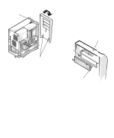
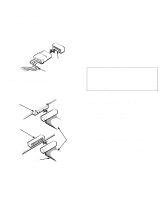
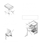
Connecting Drives When installing a drive, you connect two cables- a direct current (DC) power cable and an interface cable-to the back of the drive. Your drive's power input connector (to which you connect the DC power cable) resembles the connector shown in Figure 7-4. power input connector DC power cable Figure 7-4. DC Power Cable Connector The drive's interface connector is a card-edge connector or a header connector, as shown in Figure 7-5. card-edge connector on drive header connector on drive interface cable colored strip Figure 7-5. Drive Interface Connectors When attaching the interface cable to a drive, be sure to match the colored strip on the cable to pin 1 of the drive's interface connector. For the location of pin 1 on the drive's interface connector, see the documentation that came with the drive. Most interface connectors are keyed for correct insertion; that is, a notch or a missing pin on one connector matches a tab or a filled-in hole on the other connector (see Figure 7-5). Keying ensures that the pin-1 wire in the cable (indicated by the colored strip along one edge of the cable) goes to the pin-1 end of the connector. The pin-1 end of a connector on a board or a card is usually indicated by a silk-screened "1" printed directly on the board or card. CAUTION: When connecting an interface cable, do not reverse the interface cable (do not place the colored strip away from pin 1 of the connector). Reversing the cable prevents the drive from operating and could damage the controller, the drive, or both. Installing a Drive in a 5.25-Inch Drive Bay The 5.25-inch drive bays can accommodate any of the following types of half-height drives: • A diskette drive or tape drive that uses the diskette/ tape drive interface on the system board • A CD-ROM or tape drive that uses the secondary EIDE interface on the system board • A CD-ROM or tape drive that uses its own controller card NOTE: For information on configuring, connecting, and installing SCSI drives, see "Installing SCSI Devices" found later in this chapter. Installing Drives 7-3
-
 1
1 -
2
-
3
-
4
-
5
-
6
-
7
-
8
-
9
-
10
-
11
-
12
-
13
-
14
-
15
-
16
-
17
-
18
-
19
-
20
-
21
-
22
-
23
-
24
-
25
-
26
-
27
-
28
-
29
-
30
-
31
-
32
-
33
-
34
-
35
-
36
-
37
-
38
-
39
-
40
-
41
-
42
-
43
-
44
-
45
-
46
-
47
-
48
-
49
-
50
-
51
-
52
-
53
-
54
-
55
-
56
-
57
-
58
-
59
-
60
-
61
-
62
-
63
-
64
-
65
-
66
-
67
-
68
-
69
-
70
-
71
-
72
-
73
-
74
-
75
-
 76
76 -
 77
77 -
 78
78 -
 79
79 -
 80
80 -
 81
81 -
 82
82 -
 83
83 -
 84
84 -
 85
85 -
 86
86 -
87
-
88
-
89
-
90
-
91
-
92
-
93
-
94
-
95
-
96
-
97
-
98
-
99
-
100
-
101
-
102
-
103
-
104
-
105
-
106
-
107
-
108
-
109
-
110
-
111
-
112
-
113
-
114
-
115
-
116
-
117
-
118
-
119
-
120
-
121
-
122
-
123
-
124
-
125
-
126
 |
 |
