Dell OptiPlex GXi Reference and Installation Guide ( - Page 82
Removing a Drive, Removing the Computer Cover
 |
View all Dell OptiPlex GXi manuals
Add to My Manuals
Save this manual to your list of manuals |
Page 82 highlights
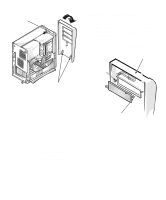
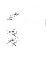
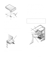
To install a drive in one of these drive bays, follow these steps: 1. Unpack the drive and prepare it for installation. Ground yourself by touching an unpainted metal surface on the back of the computer, and unpack the drive. Change any jumper or switch settings on the drive necessary for your configuration. For details about your specific drive, refer to the drive documentation included in your upgrade kit. NOTE: If you are installing a non-EIDE tape drive, check the documentation for the drive to determine the jumper or switch settings used to designate the drive as drive address DS4 (not DS2 or DS3 as may be indicated in the drive documentation). Unless the drive is already set to drive 4, reconfigure its jumper or switch setting (see "Jumpers" and "Switches" in Chapter 5). If the drive will be the second drive on the diskette/ tape drive interface cable, determine whether you need to disable termination. If you are installing an EIDE CD-ROM or EIDE tape drive, configure the drive as a master drive or single drive. 2. Remove the computer cover as instructed in "Removing the Computer Cover" in Chapter 5. CAUTION: See "Protecting Against Electrostatic Discharge" in the safety instructions at the front of this guide. 3. Remove the front bezel according to the instructions in "Removing and Replacing the Front Bezel" found earlier in this chapter. 4. Remove the drive bracket from the bay you want to use. Squeeze the metal tabs that extend from each side of the drive bracket toward each other, and pull the bracket out the bay (see Figure 7-6). NOTE: For easier access inside the chassis, you may want to rotate the power supply out of the way temporarily. To do so, see "Rotating the Power Supply Away From the System Board" in Chapter 5. bracket tabs (2) Figure 7-6. Removing a Drive If a drive is already installed in the bay and you are replacing it, be sure to disconnect the DC power cable and interface cable from the back of the drive before sliding the bracket out of the bay. To remove the old drive from the bracket, turn the drive/bracket assembly over and unscrew the four screws securing the drive to the bracket (see Figure 7-7). 5. Attach the bracket to the new drive. Turn the drive upside down and locate the four screw holes around its perimeter. Fit the bracket over the drive, and then tilt the front of the drive up so that the bracket drops down into place. To ensure proper installation, all screw holes should be aligned and the tabs on the front of the bracket should be flush with the front of the drive (see Figure 7-7). 7-4 Dell OptiPlex GXi Mini Tower Systems Reference and Installation Guide
-
 1
1 -
2
-
3
-
4
-
5
-
6
-
7
-
8
-
9
-
10
-
11
-
12
-
13
-
14
-
15
-
16
-
17
-
18
-
19
-
20
-
21
-
22
-
23
-
24
-
25
-
26
-
27
-
28
-
29
-
30
-
31
-
32
-
33
-
34
-
35
-
36
-
37
-
38
-
39
-
40
-
41
-
42
-
43
-
44
-
45
-
46
-
47
-
48
-
49
-
50
-
51
-
52
-
53
-
54
-
55
-
56
-
57
-
58
-
59
-
60
-
61
-
62
-
63
-
64
-
65
-
66
-
67
-
68
-
69
-
70
-
71
-
72
-
73
-
74
-
75
-
76
-
 77
77 -
 78
78 -
 79
79 -
 80
80 -
 81
81 -
 82
82 -
 83
83 -
 84
84 -
 85
85 -
 86
86 -
 87
87 -
88
-
89
-
90
-
91
-
92
-
93
-
94
-
95
-
96
-
97
-
98
-
99
-
100
-
101
-
102
-
103
-
104
-
105
-
106
-
107
-
108
-
109
-
110
-
111
-
112
-
113
-
114
-
115
-
116
-
117
-
118
-
119
-
120
-
121
-
122
-
123
-
124
-
125
-
126
 |
 |
