Dell OptiPlex GXi Reference and Installation Guide ( - Page 87
Inserting the Drive Bracket in, the Chassis, Attaching Hard-Disk Drive, Cables
 |
View all Dell OptiPlex GXi manuals
Add to My Manuals
Save this manual to your list of manuals |
Page 87 highlights
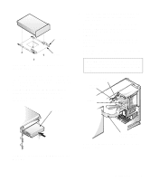
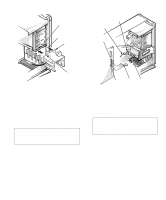
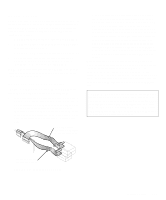
drive-cage slide rail chassis slots hinge tabs power input connector on drive DC power cable IDE2 connector sliding tab Figure 7-12. Inserting the Drive Bracket in the Chassis 8. Connect a DC power cable to the power input connector on the back of the drive (see Figure 7-13). Check all connectors to be certain that they are properly cabled and firmly seated. 9. Connect one of the device connectors on the EIDE cable to the 40-pin interface connector on the back of the hard-disk drive (see Figure 7-13). CAUTION: You must match the colored strip on the EIDE cable with pin 1 on the drive's interface connector to avoid possible damage to your system. IDE1 connector EIDE cable interface connector Figure 7-13. Attaching Hard-Disk Drive Cables 10. If it is not already connected, connect the other end of the EIDE cable to the IDE1 connector on the system board. CAUTION: You must match the colored strip on the EIDE cable with pin 1 on the IDE1 connector to avoid possible damage to your system. To locate the IDE1 connector, see Figure 6-1. 11. Replace the computer cover. Then reconnect your computer and peripherals to their power sources, and turn them on. 12. Insert a bootable diskette (such as the Dell diagnostics diskette) into drive A, and turn on the computer system. Installing Drives 7-9
-
 1
1 -
2
-
3
-
4
-
5
-
6
-
7
-
8
-
9
-
10
-
11
-
12
-
13
-
14
-
15
-
16
-
17
-
18
-
19
-
20
-
21
-
22
-
23
-
24
-
25
-
26
-
27
-
28
-
29
-
30
-
31
-
32
-
33
-
34
-
35
-
36
-
37
-
38
-
39
-
40
-
41
-
42
-
43
-
44
-
45
-
46
-
47
-
48
-
49
-
50
-
51
-
52
-
53
-
54
-
55
-
56
-
57
-
58
-
59
-
60
-
61
-
62
-
63
-
64
-
65
-
66
-
67
-
68
-
69
-
70
-
71
-
72
-
73
-
74
-
75
-
76
-
77
-
78
-
79
-
80
-
81
-
 82
82 -
 83
83 -
 84
84 -
 85
85 -
 86
86 -
 87
87 -
 88
88 -
 89
89 -
 90
90 -
 91
91 -
 92
92 -
93
-
94
-
95
-
96
-
97
-
98
-
99
-
100
-
101
-
102
-
103
-
104
-
105
-
106
-
107
-
108
-
109
-
110
-
111
-
112
-
113
-
114
-
115
-
116
-
117
-
118
-
119
-
120
-
121
-
122
-
123
-
124
-
125
-
126
 |
 |
