Dell OptiPlex GXi Reference and Installation Guide ( - Page 79
Installing Drives, Removing and Replacing the Front Bezel, Drive Locations
 |
View all Dell OptiPlex GXi manuals
Add to My Manuals
Save this manual to your list of manuals |
Page 79 highlights
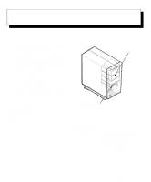
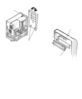
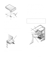
Chapter 7 Installing Drives Your Dell computer has six drive bays for installing the following types of drives (see Figure 7-1): • The externally accessible drive bays at the front of the computer consist of one 3.5-inch drive bay (dedicated to a 3.5-inch diskette drive) and three 5.25-inch bays that can hold up to three half-height, 5.25-inch devices-typically tape drives or CD-ROM drives. Alternately, 3.5-inch devices can be installed in the 5.25-inch bays using adapters available from Dell. • The two hard-disk drive bays can each hold a 3.5-inch enhanced integrated drive electronics (EIDE) or small computer system interface (SCSI) hard-disk drive. Together, the bays can hold one 1-inch-high (or smaller) drive and one 1.6-inch-high (or smaller) drive. The next three sections contain information that you will need in several of the installation procedures described later in the chapter. The remaining sections of this chapter cover each type of drive installation. NOTE: In all of the following procedures, left and right refer to your left and right as you face the front of the computer. externally accessible drive bays two-bay hard-disk drive area (internal) Figure 7-1. Drive Locations Removing and Replacing the Front Bezel The bezel is secured to the front of the chassis by two tabs and two hooks. The tab release for the bezel is at the top of the computer chassis and can be accessed only with the computer cover removed. With the cover removed, release the bezel by pressing the tab release marked with the icon (see Figure 7-2). Installing Drives 7-1
-
 1
1 -
2
-
3
-
4
-
5
-
6
-
7
-
8
-
9
-
10
-
11
-
12
-
13
-
14
-
15
-
16
-
17
-
18
-
19
-
20
-
21
-
22
-
23
-
24
-
25
-
26
-
27
-
28
-
29
-
30
-
31
-
32
-
33
-
34
-
35
-
36
-
37
-
38
-
39
-
40
-
41
-
42
-
43
-
44
-
45
-
46
-
47
-
48
-
49
-
50
-
51
-
52
-
53
-
54
-
55
-
56
-
57
-
58
-
59
-
60
-
61
-
62
-
63
-
64
-
65
-
66
-
67
-
68
-
69
-
70
-
71
-
72
-
73
-
 74
74 -
 75
75 -
 76
76 -
 77
77 -
 78
78 -
 79
79 -
 80
80 -
 81
81 -
 82
82 -
 83
83 -
 84
84 -
85
-
86
-
87
-
88
-
89
-
90
-
91
-
92
-
93
-
94
-
95
-
96
-
97
-
98
-
99
-
100
-
101
-
102
-
103
-
104
-
105
-
106
-
107
-
108
-
109
-
110
-
111
-
112
-
113
-
114
-
115
-
116
-
117
-
118
-
119
-
120
-
121
-
122
-
123
-
124
-
125
-
126
 |
 |
