Dell OptiPlex GXi Reference and Installation Guide ( - Page 75
Installing the Microprocessor, Installing the Heat Sink
 |
View all Dell OptiPlex GXi manuals
Add to My Manuals
Save this manual to your list of manuals |
Page 75 highlights
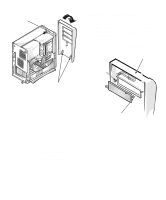
When the chip is fully seated in the socket, pivot the microprocessor-socket release lever back toward the socket until it snaps into place, securing the chip. clip heat sink pin-1 corners of chip and socket aligned Figure 6-12. Installing the Microprocessor Chip 9. Unpack the heat sink included in your upgrade kit. Peel the release liner from the adhesive tape that is attached to the bottom of the heat sink. 10. Place the heat sink on top of the microprocessor chip (see Figure 6-13). microprocessor chip microprocessor socket Figure 6-13. Installing the Heat Sink 11. Replace the heat sink securing clip. Orient the clip as shown in Figure 6-13, and hook the unfolded end of the clip over the tab on the top edge of the socket. Then press down on the folded end of the clip to snap the clip over the tab on the bottom edge of the socket. Installing System Board Options 6-9
-
 1
1 -
2
-
3
-
4
-
5
-
6
-
7
-
8
-
9
-
10
-
11
-
12
-
13
-
14
-
15
-
16
-
17
-
18
-
19
-
20
-
21
-
22
-
23
-
24
-
25
-
26
-
27
-
28
-
29
-
30
-
31
-
32
-
33
-
34
-
35
-
36
-
37
-
38
-
39
-
40
-
41
-
42
-
43
-
44
-
45
-
46
-
47
-
48
-
49
-
50
-
51
-
52
-
53
-
54
-
55
-
56
-
57
-
58
-
59
-
60
-
61
-
62
-
63
-
64
-
65
-
66
-
67
-
68
-
69
-
 70
70 -
 71
71 -
 72
72 -
 73
73 -
 74
74 -
 75
75 -
 76
76 -
 77
77 -
 78
78 -
 79
79 -
 80
80 -
81
-
82
-
83
-
84
-
85
-
86
-
87
-
88
-
89
-
90
-
91
-
92
-
93
-
94
-
95
-
96
-
97
-
98
-
99
-
100
-
101
-
102
-
103
-
104
-
105
-
106
-
107
-
108
-
109
-
110
-
111
-
112
-
113
-
114
-
115
-
116
-
117
-
118
-
119
-
120
-
121
-
122
-
123
-
124
-
125
-
126
 |
 |
