Dell OptiPlex GXi Reference and Installation Guide ( - Page 85
EIDE Drive Addressing, Installing an EIDE Hard-Disk Drive in the Hard-Dis...
 |
View all Dell OptiPlex GXi manuals
Add to My Manuals
Save this manual to your list of manuals |
Page 85 highlights
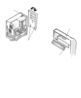
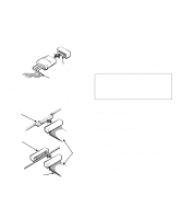
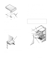
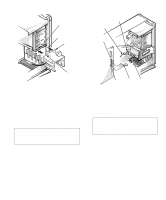
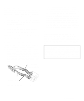
EIDE Drive Addressing When two EIDE devices are connected to a single EIDE interface cable, a master/slave relationship must be defined between the two devices so that they will operate correctly while cabled together. The boot EIDE drive should be configured as the master drive connected to the EIDE interface on the system board. Before installing a second EIDE drive, you must designate it as the slave drive. Assigning the master and slave designations usually involves resetting jumpers on the circuit card on the underside of each drive. The master/slave relationship is defined in different ways for different types of drives. For details about your specific drive, refer to the drive documentation included in your upgrade kit. That document describes how to reconfigure both drives to ensure correct operation. NOTE: If you want to install a second EIDE drive that is a different type from the first drive but you do not have the specifications for the first drive, do one of the following: • If you purchased the drive from Dell, you can contact Dell for the necessary reconfiguration information. (See the chapter titled "Getting Help" in the Diagnostics and Troubleshooting Guide for instructions on obtaining technical assistance.) • If you did not purchase the drive from Dell, call the drive manufacturer. With the two EIDE interface connectors on the system board, your system can support up to four EIDE devices. EIDE hard-disk drives should be connected to the EIDE interface connector labeled "IDE1." (EIDE tape drives and CD-ROM drives should be connected to the EIDE interface connector labeled "IDE2.") Installing an EIDE Hard-Disk Drive in the Hard-Disk Drive Bracket Install an EIDE hard-disk drive in the hard-disk drive bracket as follows: 1. If you are replacing a hard-disk drive that contains data you want to keep, be sure to make a backup of your files before you begin this procedure. 2. Prepare the drive for installation. Ground yourself by touching an unpainted metal surface on the back of the computer, and unpack the drive. Check the documentation that accompanied the drive to verify that it is configured for your computer system. 3. Remove the computer cover as instructed in "Removing the Computer Cover" in Chapter 5. CAUTION: See "Protecting Against Electrostatic Discharge" in the safety instructions at the front of this guide. 4. Remove the drive bracket from the chassis. If a hard-disk drive is already installed in the drive bracket, disconnect the DC power cable and EIDE cable from the drive. Remove the screw securing the hard-disk drive bracket to the drive cage in the chassis. Grasp the bracket and rotate it outward from the chassis until the sliding tab clears the slide rail on the drive cage (see Figure 7-10). Lift the bracket up slightly to free its hinge tabs from the chassis slots. Installing Drives 7-7
-
 1
1 -
2
-
3
-
4
-
5
-
6
-
7
-
8
-
9
-
10
-
11
-
12
-
13
-
14
-
15
-
16
-
17
-
18
-
19
-
20
-
21
-
22
-
23
-
24
-
25
-
26
-
27
-
28
-
29
-
30
-
31
-
32
-
33
-
34
-
35
-
36
-
37
-
38
-
39
-
40
-
41
-
42
-
43
-
44
-
45
-
46
-
47
-
48
-
49
-
50
-
51
-
52
-
53
-
54
-
55
-
56
-
57
-
58
-
59
-
60
-
61
-
62
-
63
-
64
-
65
-
66
-
67
-
68
-
69
-
70
-
71
-
72
-
73
-
74
-
75
-
76
-
77
-
78
-
79
-
 80
80 -
 81
81 -
 82
82 -
 83
83 -
 84
84 -
 85
85 -
 86
86 -
 87
87 -
 88
88 -
 89
89 -
 90
90 -
91
-
92
-
93
-
94
-
95
-
96
-
97
-
98
-
99
-
100
-
101
-
102
-
103
-
104
-
105
-
106
-
107
-
108
-
109
-
110
-
111
-
112
-
113
-
114
-
115
-
116
-
117
-
118
-
119
-
120
-
121
-
122
-
123
-
124
-
125
-
126
 |
 |
