Dell PowerEdge M520 Dell Converged Enhanced Ethernet Administrator's Guide - Page 126
TABLE 22, Default CEE Priority Group Table configuration, Default CEE priority table
 |
View all Dell PowerEdge M520 manuals
Add to My Manuals
Save this manual to your list of manuals |
Page 126 highlights
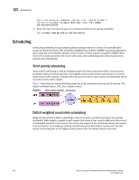
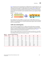
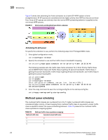
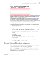
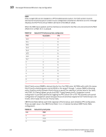
10 Converged Enhanced Ethernet map configuration NOTE Only a single CoS can be mapped to a PFC-enabled priority queue. The CoS number must be identical to the priority queue number. If your configuration violates this restriction an error message displays and the Priority Group Table is set back to the default values. When the CEE map is applied, and the interface is connected to the CNA, only one strict priority PGID (PGID 15.0 to PGID 15.7) is allowed. TABLE 22 PGID Default CEE Priority Group Table configuration Bandwidth% PFC 15.0 15.1 15.2 15.3 15.4 15.5 15.6 15.7 0 1 2 3 4 5 6 7 - N - N - N - N - N - N - N - N 0 N 0 N 0 N 0 N 0 N 0 N 0 N 0 N Strict Priority versus DWRR is derived directly from the PGID value. All PGIDs with prefix 15 receive Strict Priority scheduling policy and all PGIDs in the range 0 through 7 receive DWRR scheduling policy. Relative priority between Priority Group is exactly the ordering of entries listed in the table, with PGID 15.0 being highest priority and PGID 7 being lowest priority. Congestion control configuration is partially specified by toggling the PFC column On or Off. This provides only partial configuration of congestion control because the set of priorities mapped to the Priority Group is not known, which leads into the CEE Priority Table. CEE Priority Table defines each CoS mapping to Priority Group, and completes PFC configuration. There are eight rows in the CEE Priority Table. Table 23 details the default CEE Priority Table configuration. TABLE 23 CoS Default CEE priority table PGID 0 15.7 1 15.6 2 15.5 108 Dell Converged Enhanced Ethernet Administrator's Guide 53-1002116-01
-
 1
1 -
2
-
3
-
4
-
5
-
6
-
7
-
8
-
9
-
10
-
11
-
12
-
13
-
14
-
15
-
16
-
17
-
18
-
19
-
20
-
21
-
22
-
23
-
24
-
25
-
26
-
27
-
28
-
29
-
30
-
31
-
32
-
33
-
34
-
35
-
36
-
37
-
38
-
39
-
40
-
41
-
42
-
43
-
44
-
45
-
46
-
47
-
48
-
49
-
50
-
51
-
52
-
53
-
54
-
55
-
56
-
57
-
58
-
59
-
60
-
61
-
62
-
63
-
64
-
65
-
66
-
67
-
68
-
69
-
70
-
71
-
72
-
73
-
74
-
75
-
76
-
77
-
78
-
79
-
80
-
81
-
82
-
83
-
84
-
85
-
86
-
87
-
88
-
89
-
90
-
91
-
92
-
93
-
94
-
95
-
96
-
97
-
98
-
99
-
100
-
101
-
102
-
103
-
104
-
105
-
106
-
107
-
108
-
109
-
110
-
111
-
112
-
113
-
114
-
115
-
116
-
117
-
118
-
119
-
120
-
 121
121 -
 122
122 -
 123
123 -
 124
124 -
 125
125 -
 126
126 -
 127
127 -
 128
128 -
 129
129 -
 130
130 -
 131
131 -
132
-
133
-
134
-
135
-
136
-
137
-
138
-
139
-
140
-
141
-
142
-
143
-
144
-
145
-
146
-
147
-
148
-
149
-
150
-
151
-
152
-
153
-
154
-
155
-
156
-
157
-
158
-
159
-
160
-
161
-
162
-
163
-
164
-
165
-
166
-
167
-
168
 |
 |