Dell PowerEdge M520 Dell Converged Enhanced Ethernet Administrator's Guide - Page 96
DCBX overview, Enhanced Transmission Selection (ETS)
 |
View all Dell PowerEdge M520 manuals
Add to My Manuals
Save this manual to your list of manuals |
Page 96 highlights
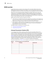
8 DCBX overview DCBX overview Storage traffic requires a lossless communication which is provided by CEE. The Data Center Bridging (DCB) Capability Exchange Protocol (DCBX) is used to exchange CEE-related parameters with neighbors to achieve more efficient scheduling and a priority-based flow control for link traffic. DCBX uses LLDP to exchange parameters between two link peers; DCBX is built on the LLDP infrastructure for the exchange of information. DCBX-exchanged parameters are packaged into organizationally specific TLVs. The DCBX protocol requires an acknowledgement from the other side of the link, therefore LLDP is turned on in both transmit and receive directions. DCBX requires version number checking for both control TLVs and feature TLVs. DCBX interacts with other protocols and features as follows: • LLDP-LLDP is run in parallel with other Layer 2 protocols such as RSTP and LACP. DCBX is built on the LLDP infrastructure to communicate capabilities supported between link partners. The DCBX protocol and feature TLVs are treated as a superset of the LLDP standard. • QoS management-DCBX capabilities exchanged with a link partner are passed down to the QoS management entity to set up the Dell FCoE hardware to control the scheduling and priority-based flow control in the hardware. The DCBX standard is subdivided into two features sets: • "Enhanced Transmission Selection (ETS)" • "Priority Flow Control (PFC)" Enhanced Transmission Selection (ETS) In a converged network, different traffic types affect the network bandwidth differently. The purpose of ETS is to allocate bandwidth based on the different priority settings of the converged traffic. For example, Inter-process communications (IPC) traffic can use as much bandwidth as needed and there is no bandwidth check; LAN and SAN traffic share the remaining bandwidth. Table 13 displays three traffic groups: IPC, LAN, and SAN. ETS allocates the bandwidth based on traffic type and also assigns a priority to the three traffic types as follows: Priority 7 traffic is mapped to priority group 0 which does not get a bandwidth check, priority 2 and priority 3 are mapped to priority group 1, priorities 6, 5, 4, 1 and 0 are mapped to priority group 2. The priority settings shown in Table 13 are translated to priority groups in the Dell FCoE hardware. TABLE 13 Priority ETS priority grouping of IPC, LAN, and SAN traffic Priority group Bandwidth check 7 0 No 6 2 Yes 5 2 Yes 4 2 Yes 3 1 Yes 2 1 Yes 1 2 Yes 0 2 Yes 78 Dell Converged Enhanced Ethernet Administrator's Guide 53-1002116-01
-
 1
1 -
2
-
3
-
4
-
5
-
6
-
7
-
8
-
9
-
10
-
11
-
12
-
13
-
14
-
15
-
16
-
17
-
18
-
19
-
20
-
21
-
22
-
23
-
24
-
25
-
26
-
27
-
28
-
29
-
30
-
31
-
32
-
33
-
34
-
35
-
36
-
37
-
38
-
39
-
40
-
41
-
42
-
43
-
44
-
45
-
46
-
47
-
48
-
49
-
50
-
51
-
52
-
53
-
54
-
55
-
56
-
57
-
58
-
59
-
60
-
61
-
62
-
63
-
64
-
65
-
66
-
67
-
68
-
69
-
70
-
71
-
72
-
73
-
74
-
75
-
76
-
77
-
78
-
79
-
80
-
81
-
82
-
83
-
84
-
85
-
86
-
87
-
88
-
89
-
90
-
 91
91 -
 92
92 -
 93
93 -
 94
94 -
 95
95 -
 96
96 -
 97
97 -
 98
98 -
 99
99 -
 100
100 -
 101
101 -
102
-
103
-
104
-
105
-
106
-
107
-
108
-
109
-
110
-
111
-
112
-
113
-
114
-
115
-
116
-
117
-
118
-
119
-
120
-
121
-
122
-
123
-
124
-
125
-
126
-
127
-
128
-
129
-
130
-
131
-
132
-
133
-
134
-
135
-
136
-
137
-
138
-
139
-
140
-
141
-
142
-
143
-
144
-
145
-
146
-
147
-
148
-
149
-
150
-
151
-
152
-
153
-
154
-
155
-
156
-
157
-
158
-
159
-
160
-
161
-
162
-
163
-
164
-
165
-
166
-
167
-
168
 |
 |