Dell PowerEdge R350 EMC Installation and Service Manual - Page 33
Removing the backplane, x 2.5-inch drive backplane
 |
View all Dell PowerEdge R350 manuals
Add to My Manuals
Save this manual to your list of manuals |
Page 33 highlights
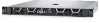
Figure 20. 8 x 2.5-inch drive backplane 1. BP_PWR_1 (backplane power and signal cable to PIB) 2. BP_DST_SA1 (SAS/SATA connector) 3. BP_PWR_CTRL (backplane power) Removing the backplane Prerequisites CAUTION: To prevent damage to the drives and backplane, remove the drives from the system before removing the backplane. CAUTION: Note the number of each drive and temporarily label them before you remove the drive so that you can reinstall them in the same location. NOTE: The procedure to remove the backplane is similar for all backplane configurations. 1. Follow the safety guidelines listed in the Safety instructions. 2. Follow the procedure listed in the Before working inside your system. 3. Remove the air shroud. 4. Remove all the drives. 5. If installed, disconnect the optical drive signal and power cables from the system. NOTE: Observe the routing of the cable as you remove it from the system. 6. Disconnect the drive backplane cables from the connectors on the system board. Steps 1. Press the blue release tabs to disengage the drive backplane from the hooks on the system. 2. Lift the drive backplane out of the system. NOTE: To avoid damaging the backplane, ensure that you move the control panel cables from the cable routing clips before removing the backplane. Installing and removing system components 33
-
 1
1 -
2
-
3
-
4
-
5
-
6
-
7
-
8
-
9
-
10
-
11
-
12
-
13
-
14
-
15
-
16
-
17
-
18
-
19
-
20
-
21
-
22
-
23
-
24
-
25
-
26
-
27
-
 28
28 -
 29
29 -
 30
30 -
 31
31 -
 32
32 -
 33
33 -
 34
34 -
 35
35 -
 36
36 -
 37
37 -
 38
38 -
39
-
40
-
41
-
42
-
43
-
44
-
45
-
46
-
47
-
48
-
49
-
50
-
51
-
52
-
53
-
54
-
55
-
56
-
57
-
58
-
59
-
60
-
61
-
62
-
63
-
64
-
65
-
66
-
67
-
68
-
69
-
70
-
71
-
72
-
73
-
74
-
75
-
76
-
77
-
78
-
79
-
80
-
81
-
82
-
83
-
84
-
85
-
86
-
87
-
88
-
89
-
90
-
91
-
92
-
93
-
94
-
95
-
96
-
97
-
98
-
99
-
100
-
101
-
102
-
103
-
104
-
105
-
106
 |
 |
