Dell PowerEdge R350 EMC Installation and Service Manual - Page 87
Installing the left control panel
 |
View all Dell PowerEdge R350 manuals
Add to My Manuals
Save this manual to your list of manuals |
Page 87 highlights
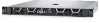
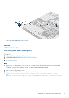
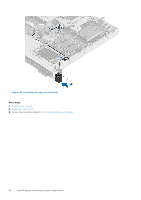
Figure 80. Removing the left control panel Next steps Replace the left control panel. Installing the left control panel Prerequisites 1. Follow the safety guidelines listed in the Safety instructions. 2. Follow the procedure listed in Before working inside your system. 3. Remove the front bezel. 4. Remove the air shroud. Steps 1. Route the control panel cable through the cable clip, the guide slots in the system and connector on system board. NOTE: Route the cable properly to prevent the cable from being pinched or crimped. 2. Close and secure the cable guiding latch. 3. Align and insert the left control panel assembly in the slot on the system. 4. Using the Phillips #1 screwdriver, tighten the screws that secure the left control panel assembly to the system. NOTE: The numbers on the image do not depict the exact steps. The numbers are for representation of sequence. Installing and removing system components 87
-
 1
1 -
2
-
3
-
4
-
5
-
6
-
7
-
8
-
9
-
10
-
11
-
12
-
13
-
14
-
15
-
16
-
17
-
18
-
19
-
20
-
21
-
22
-
23
-
24
-
25
-
26
-
27
-
28
-
29
-
30
-
31
-
32
-
33
-
34
-
35
-
36
-
37
-
38
-
39
-
40
-
41
-
42
-
43
-
44
-
45
-
46
-
47
-
48
-
49
-
50
-
51
-
52
-
53
-
54
-
55
-
56
-
57
-
58
-
59
-
60
-
61
-
62
-
63
-
64
-
65
-
66
-
67
-
68
-
69
-
70
-
71
-
72
-
73
-
74
-
75
-
76
-
77
-
78
-
79
-
80
-
81
-
 82
82 -
 83
83 -
 84
84 -
 85
85 -
 86
86 -
 87
87 -
 88
88 -
 89
89 -
 90
90 -
 91
91 -
 92
92 -
93
-
94
-
95
-
96
-
97
-
98
-
99
-
100
-
101
-
102
-
103
-
104
-
105
-
106
 |
 |
