Dell PowerEdge R720 Owner's Manual - Page 17
Four integrated 10/100/1000 Mbps NIC connectors - rack for
 |
View all Dell PowerEdge R720 manuals
Add to My Manuals
Save this manual to your list of manuals |
Page 17 highlights
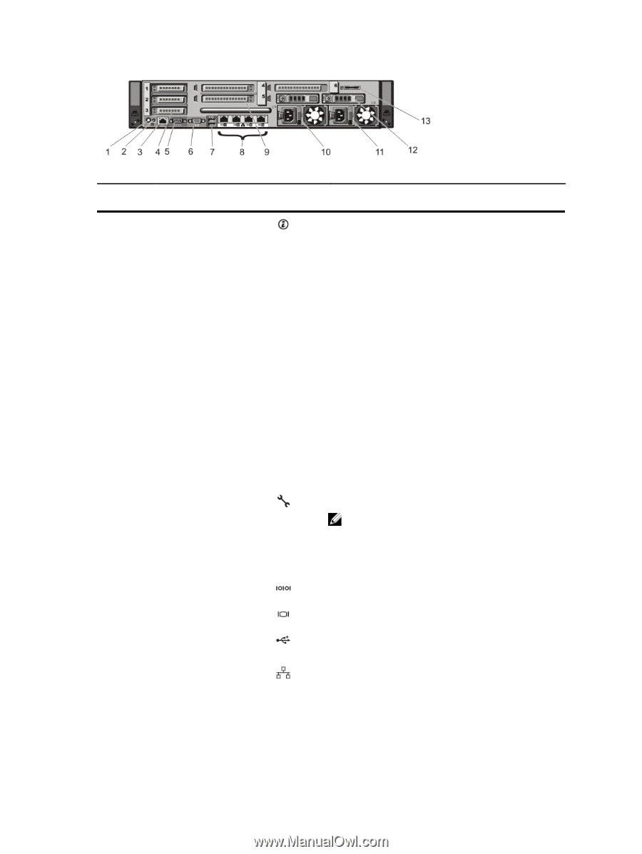
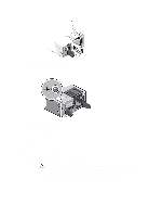
Figure 8. Back-Panel Features and Indicators-PowerEdge R720xd Item Indicator, Button, or Icon Description Connector 1 System identification button The identification buttons on the front and back panels can be used to locate a particular system within a rack. PowerEdge R720 PowerEdge R720xd When one of these buttons is pressed, the LCD panel on the front and the system status indicator on the back flashes until one of the buttons is pressed again. When one of these buttons is pressed, the system status indicator on the back flashes until one of the buttons is pressed again. 2 System identification connector 3 iDRAC7 Enterprise port Press to toggle the system ID on and off. If the system stops responding during POST, press and hold the system ID button for more than five seconds to enter BIOS progress mode. To reset iDRAC (if not disabled in F2 iDRAC setup) press and hold the button for more than 15 seconds. Connects the optional system status indicator assembly through the optional cable management arm. Dedicated management port. NOTE: The port is available for use only if the iDRAC7 Enterprise license is installed on your system. 4 PCIe expansion card slots low-profile (3) 5 Serial connector Allows you to connect up to three PCI Express expansion cards. Allows you to connect a serial device to the system. 6 Video connector Allows you to connect a VGA display to the system. 7 USB connectors (2) 8 Ethernet connectors Allows you to connect USB devices to the system. The ports are USB 2.0-compliant. Four integrated 10/100/1000 Mbps NIC connectors or Four integrated connectors that include: • Two 10/100/1000 Mbps NIC connectors 17
-
 1
1 -
2
-
3
-
4
-
5
-
6
-
7
-
8
-
9
-
10
-
11
-
 12
12 -
 13
13 -
 14
14 -
 15
15 -
 16
16 -
 17
17 -
 18
18 -
 19
19 -
 20
20 -
 21
21 -
 22
22 -
23
-
24
-
25
-
26
-
27
-
28
-
29
-
30
-
31
-
32
-
33
-
34
-
35
-
36
-
37
-
38
-
39
-
40
-
41
-
42
-
43
-
44
-
45
-
46
-
47
-
48
-
49
-
50
-
51
-
52
-
53
-
54
-
55
-
56
-
57
-
58
-
59
-
60
-
61
-
62
-
63
-
64
-
65
-
66
-
67
-
68
-
69
-
70
-
71
-
72
-
73
-
74
-
75
-
76
-
77
-
78
-
79
-
80
-
81
-
82
-
83
-
84
-
85
-
86
-
87
-
88
-
89
-
90
-
91
-
92
-
93
-
94
-
95
-
96
-
97
-
98
-
99
-
100
-
101
-
102
-
103
-
104
-
105
-
106
-
107
-
108
-
109
-
110
-
111
-
112
-
113
-
114
-
115
-
116
-
117
-
118
-
119
-
120
-
121
-
122
-
123
-
124
-
125
-
126
-
127
-
128
-
129
-
130
-
131
-
132
-
133
-
134
-
135
-
136
-
137
-
138
-
139
-
140
-
141
-
142
-
143
-
144
-
145
-
146
-
147
-
148
-
149
-
150
-
151
-
152
-
153
-
154
-
155
-
156
-
157
 |
 |