Dell PowerEdge R720 Owner's Manual - Page 64
GPU Host Interface Card, Flash PCIe SSD Bridge - nic teaming
 |
View all Dell PowerEdge R720 manuals
Add to My Manuals
Save this manual to your list of manuals |
Page 64 highlights
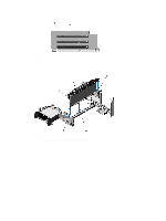
NOTE: The expansion-card slots are not hot-swappable. The following table provides guidelines for installing expansion cards to ensure proper cooling and mechanical fit. The expansion cards with the highest priority should be installed first using the slot priority indicated. All other expansion cards should be installed in card priority and slot priority order. Table 4. Expansion Card Installation Order Card Priority Card Type Slot Priority-PowerEdge Slot Priority-PowerEdge Max Allowed R720 R720xd 1 Dell PowerEdge Express 4 Flash (PCIe SSD) Bridge Not Supported 1 2 GPU (single wide) 4, 6, 7, 5 Not Supported 4 GPU (double wide) 6, 4 Not Supported 2 3 GPU Host Interface Card 4, 6 (HIC) Not Supported 2 4 RAID H710P 2 Not Supported 1 RAID H810 7, 6, 4, 5 6, 4, 5 2 5 Converged Network 5, 7, 4, 6 4, 6, 5 4 Adapters (CNAs) 6 10 Gb NICs 5, 7, 4, 6 4, 6, 5 4 7 FC4/8 HBA 5, 7, 4, 6 4, 6, 5 4 2, 3, 1 2, 3, 1 8 1 Gb NICs 5, 7, 4, 6 4, 6, 5 4 2, 3, 1 2, 3, 1 9 Non-RAID 5, 7, 4, 6 4, 6, 5 4 2, 3, 1 2, 3, 1 Removing An Expansion Card From The Expansion-Card Riser 2 Or 3 CAUTION: Many repairs may only be done by a certified service technician. You should only perform troubleshooting and simple repairs as authorized in your product documentation, or as directed by the online or telephone service and support team. Damage due to servicing that is not authorized by Dell is not covered by your warranty. Read and follow the safety instructions that came with the product. 1. Turn off the system, including any attached peripherals, and disconnect the system from the electrical outlet and peripherals. 2. Open the system. 3. Disconnect any cables connected to the expansion card. 4. Lift the expansion-card latch out of the slot. 5. Grasp the expansion card by its edges, and remove it from the expansion-card connector. 6. If you are removing the card permanently, install a metal filler bracket over the empty expansion slot opening and close the expansion-card latch. 64
-
 1
1 -
2
-
3
-
4
-
5
-
6
-
7
-
8
-
9
-
10
-
11
-
12
-
13
-
14
-
15
-
16
-
17
-
18
-
19
-
20
-
21
-
22
-
23
-
24
-
25
-
26
-
27
-
28
-
29
-
30
-
31
-
32
-
33
-
34
-
35
-
36
-
37
-
38
-
39
-
40
-
41
-
42
-
43
-
44
-
45
-
46
-
47
-
48
-
49
-
50
-
51
-
52
-
53
-
54
-
55
-
56
-
57
-
58
-
 59
59 -
 60
60 -
 61
61 -
 62
62 -
 63
63 -
 64
64 -
 65
65 -
 66
66 -
 67
67 -
 68
68 -
 69
69 -
70
-
71
-
72
-
73
-
74
-
75
-
76
-
77
-
78
-
79
-
80
-
81
-
82
-
83
-
84
-
85
-
86
-
87
-
88
-
89
-
90
-
91
-
92
-
93
-
94
-
95
-
96
-
97
-
98
-
99
-
100
-
101
-
102
-
103
-
104
-
105
-
106
-
107
-
108
-
109
-
110
-
111
-
112
-
113
-
114
-
115
-
116
-
117
-
118
-
119
-
120
-
121
-
122
-
123
-
124
-
125
-
126
-
127
-
128
-
129
-
130
-
131
-
132
-
133
-
134
-
135
-
136
-
137
-
138
-
139
-
140
-
141
-
142
-
143
-
144
-
145
-
146
-
147
-
148
-
149
-
150
-
151
-
152
-
153
-
154
-
155
-
156
-
157
 |
 |
