Dell PowerEdge R720 Owner's Manual - Page 67
Installing An Expansion Card Into The Expansion-Card Riser 1
 |
View all Dell PowerEdge R720 manuals
Add to My Manuals
Save this manual to your list of manuals |
Page 67 highlights
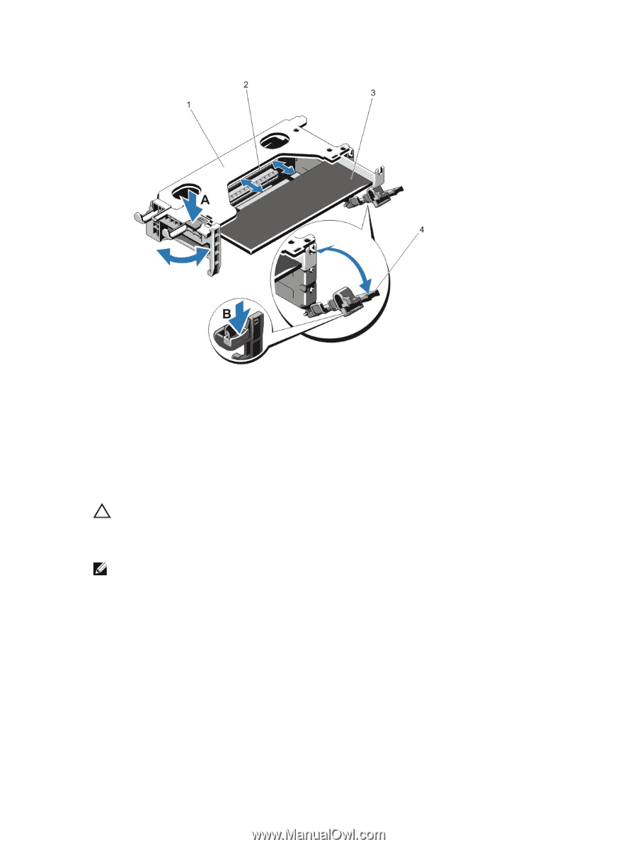
Figure 32. Removing and Installing the Expansion-Card Riser 1 1. expansion-card riser 1 cage 2. expansion-card connector 3. expansion card 4. expansion-card latches (2) Installing An Expansion Card Into The Expansion-Card Riser 1 CAUTION: Many repairs may only be done by a certified service technician. You should only perform troubleshooting and simple repairs as authorized in your product documentation, or as directed by the online or telephone service and support team. Damage due to servicing that is not authorized by Dell is not covered by your warranty. Read and follow the safety instructions that came with the product. NOTE: The expansion-card riser 1 can be used only when both the processors are installed. 1. Unpack the expansion card and prepare it for installation. For instructions, see the documentation accompanying the card. 2. Turn off the system, including any attached peripherals, and disconnect the system from the electrical outlet and peripherals. 3. Open the system. 4. Remove the expansion-card riser. 5. Press tab A and rotate the latch clockwise. 6. Press tab B and rotate the latch down. 7. Holding the card by its edges, position the card so that the card-edge connector aligns with the expansion-card connector. 67
-
 1
1 -
2
-
3
-
4
-
5
-
6
-
7
-
8
-
9
-
10
-
11
-
12
-
13
-
14
-
15
-
16
-
17
-
18
-
19
-
20
-
21
-
22
-
23
-
24
-
25
-
26
-
27
-
28
-
29
-
30
-
31
-
32
-
33
-
34
-
35
-
36
-
37
-
38
-
39
-
40
-
41
-
42
-
43
-
44
-
45
-
46
-
47
-
48
-
49
-
50
-
51
-
52
-
53
-
54
-
55
-
56
-
57
-
58
-
59
-
60
-
61
-
 62
62 -
 63
63 -
 64
64 -
 65
65 -
 66
66 -
 67
67 -
 68
68 -
 69
69 -
 70
70 -
 71
71 -
 72
72 -
73
-
74
-
75
-
76
-
77
-
78
-
79
-
80
-
81
-
82
-
83
-
84
-
85
-
86
-
87
-
88
-
89
-
90
-
91
-
92
-
93
-
94
-
95
-
96
-
97
-
98
-
99
-
100
-
101
-
102
-
103
-
104
-
105
-
106
-
107
-
108
-
109
-
110
-
111
-
112
-
113
-
114
-
115
-
116
-
117
-
118
-
119
-
120
-
121
-
122
-
123
-
124
-
125
-
126
-
127
-
128
-
129
-
130
-
131
-
132
-
133
-
134
-
135
-
136
-
137
-
138
-
139
-
140
-
141
-
142
-
143
-
144
-
145
-
146
-
147
-
148
-
149
-
150
-
151
-
152
-
153
-
154
-
155
-
156
-
157
 |
 |