Dell PowerEdge T620 Owner's Manual - Page 110
Installing The LCD Module—Rack Mode, VGA Module
 |
View all Dell PowerEdge T620 manuals
Add to My Manuals
Save this manual to your list of manuals |
Page 110 highlights
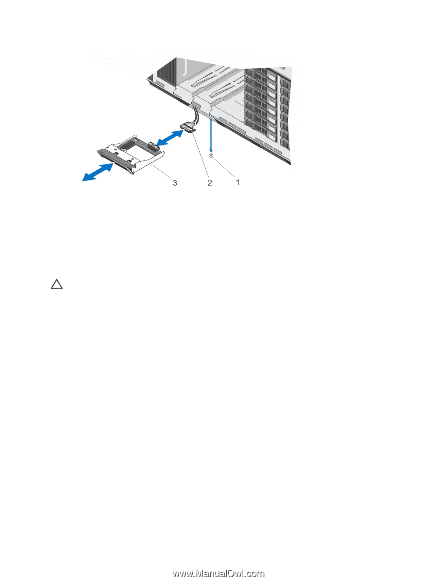
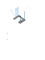
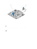
Figure 60. Removing and Installing the LCD Module in the Rack Mode 1. screw 2. LCD cable 3. LCD module Installing The LCD Module-Rack Mode CAUTION: Many repairs may only be done by a certified service technician. You should only perform troubleshooting and simple repairs as authorized in your product documentation, or as directed by the online or telephone service and support team. Damage due to servicing that is not authorized by Dell is not covered by your warranty. Read and follow the safety instructions that came with the product. 1. Route the LCD cable through the cable securing bracket and through the inside wall of the chassis next to the LCD module slot. 2. If applicable, remove the LCD module blank. 3. Insert the LCD module into the LCD module slot. 4. Connect the LCD cable to the LCD module. 5. Replace the screw. 6. Connect the LCD cable to the system board. 7. Replace the system left side cover. See Installing The System Left Side Cover. 8. Close the system. 9. Reinstall the system in a rack. 10. Reconnect the system to its electrical outlet and turn the system on, including any attached peripherals. 11. If applicable, install the front bezel. VGA Module 110
-
 1
1 -
2
-
3
-
4
-
5
-
6
-
7
-
8
-
9
-
10
-
11
-
12
-
13
-
14
-
15
-
16
-
17
-
18
-
19
-
20
-
21
-
22
-
23
-
24
-
25
-
26
-
27
-
28
-
29
-
30
-
31
-
32
-
33
-
34
-
35
-
36
-
37
-
38
-
39
-
40
-
41
-
42
-
43
-
44
-
45
-
46
-
47
-
48
-
49
-
50
-
51
-
52
-
53
-
54
-
55
-
56
-
57
-
58
-
59
-
60
-
61
-
62
-
63
-
64
-
65
-
66
-
67
-
68
-
69
-
70
-
71
-
72
-
73
-
74
-
75
-
76
-
77
-
78
-
79
-
80
-
81
-
82
-
83
-
84
-
85
-
86
-
87
-
88
-
89
-
90
-
91
-
92
-
93
-
94
-
95
-
96
-
97
-
98
-
99
-
100
-
101
-
102
-
103
-
104
-
 105
105 -
 106
106 -
 107
107 -
 108
108 -
 109
109 -
 110
110 -
 111
111 -
 112
112 -
 113
113 -
 114
114 -
 115
115 -
116
-
117
-
118
-
119
-
120
-
121
-
122
-
123
-
124
-
125
-
126
-
127
-
128
-
129
-
130
-
131
-
132
-
133
-
134
-
135
-
136
-
137
-
138
-
139
-
140
-
141
-
142
-
143
-
144
-
145
-
146
-
147
-
148
-
149
 |
 |