Dell PowerEdge T620 Owner's Manual - Page 55
Installing The Optical Drive, Removing and Installing the Optical Drive
 |
View all Dell PowerEdge T620 manuals
Add to My Manuals
Save this manual to your list of manuals |
Page 55 highlights
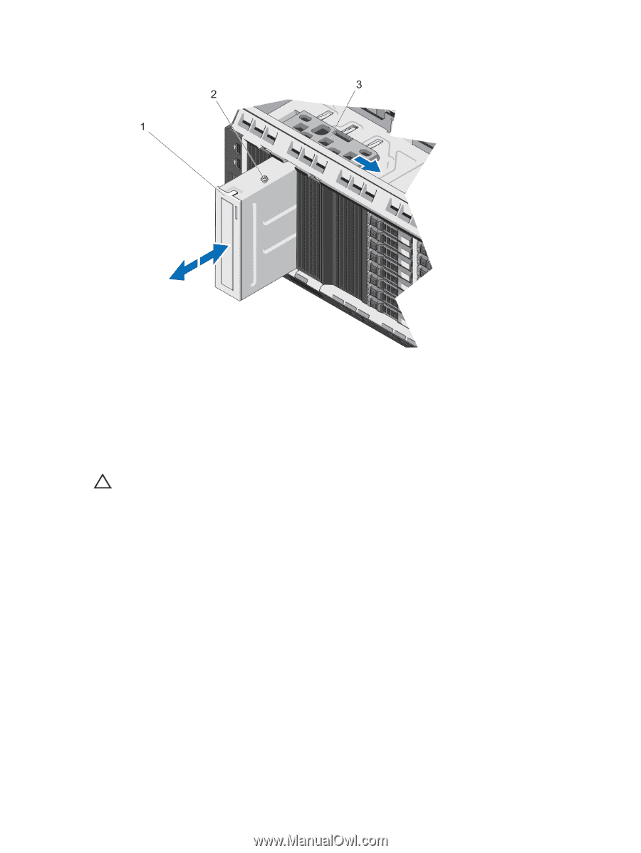
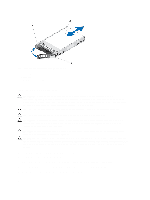
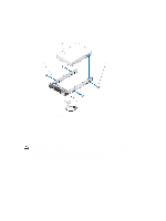
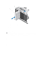
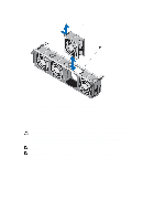
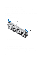
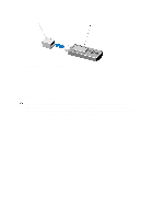
Figure 20. Removing and Installing the Optical Drive 1. optical drive 2. screw 3. release latch Installing The Optical Drive CAUTION: Many repairs may only be done by a certified service technician. You should only perform troubleshooting and simple repairs as authorized in your product documentation, or as directed by the online or telephone service and support team. Damage due to servicing that is not authorized by Dell is not covered by your warranty. Read and follow the safety instructions that came with the product. 1. If installed, remove the front bezel. 2. Turn off the system, including any attached peripherals, and disconnect the system from its electrical outlet. 3. Open the system. 4. Align the optical drive with the optical drive bay. 5. Slide the optical drive into the slot until the latch snaps into place. 6. Connect the power/data cable to the back of the drive. 7. Route the power/data cable along the inside left wall of the chassis. 8. Connect the power/data cable to the connectors on the system board. 9. Close the system. 10. If applicable, install the front bezel. 11. Reconnect the system to its electrical outlet and turn the system on, including any attached peripherals. 55
-
 1
1 -
2
-
3
-
4
-
5
-
6
-
7
-
8
-
9
-
10
-
11
-
12
-
13
-
14
-
15
-
16
-
17
-
18
-
19
-
20
-
21
-
22
-
23
-
24
-
25
-
26
-
27
-
28
-
29
-
30
-
31
-
32
-
33
-
34
-
35
-
36
-
37
-
38
-
39
-
40
-
41
-
42
-
43
-
44
-
45
-
46
-
47
-
48
-
49
-
 50
50 -
 51
51 -
 52
52 -
 53
53 -
 54
54 -
 55
55 -
 56
56 -
 57
57 -
 58
58 -
 59
59 -
 60
60 -
61
-
62
-
63
-
64
-
65
-
66
-
67
-
68
-
69
-
70
-
71
-
72
-
73
-
74
-
75
-
76
-
77
-
78
-
79
-
80
-
81
-
82
-
83
-
84
-
85
-
86
-
87
-
88
-
89
-
90
-
91
-
92
-
93
-
94
-
95
-
96
-
97
-
98
-
99
-
100
-
101
-
102
-
103
-
104
-
105
-
106
-
107
-
108
-
109
-
110
-
111
-
112
-
113
-
114
-
115
-
116
-
117
-
118
-
119
-
120
-
121
-
122
-
123
-
124
-
125
-
126
-
127
-
128
-
129
-
130
-
131
-
132
-
133
-
134
-
135
-
136
-
137
-
138
-
139
-
140
-
141
-
142
-
143
-
144
-
145
-
146
-
147
-
148
-
149
 |
 |