Dell PowerEdge T620 Owner's Manual - Page 126
System Board Connectors, B1, B5, B9, B2, B6, B10
 |
View all Dell PowerEdge T620 manuals
Add to My Manuals
Save this manual to your list of manuals |
Page 126 highlights
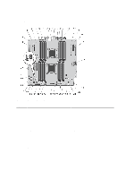
System Board Connectors Figure 63. System Board Jumpers and Connectors Item Connector 1 SLOT1 2 SLOT2 3 SLOT3 4 SLOT4 5 NIC1 6 NIC2 7 B1, B5, B9, B2, B6, B10 8 FAN1 9 ID_BTN 10 CMA_JACK 126 Description PCIe card connector 1 PCIe card connector 2 PCIe card connector 3 PCIe card connector 4 NIC1 connector NIC2 connector Memory module sockets Cooling shroud fan connector System identification button (Cable management arm) system identification connector
-
 1
1 -
2
-
3
-
4
-
5
-
6
-
7
-
8
-
9
-
10
-
11
-
12
-
13
-
14
-
15
-
16
-
17
-
18
-
19
-
20
-
21
-
22
-
23
-
24
-
25
-
26
-
27
-
28
-
29
-
30
-
31
-
32
-
33
-
34
-
35
-
36
-
37
-
38
-
39
-
40
-
41
-
42
-
43
-
44
-
45
-
46
-
47
-
48
-
49
-
50
-
51
-
52
-
53
-
54
-
55
-
56
-
57
-
58
-
59
-
60
-
61
-
62
-
63
-
64
-
65
-
66
-
67
-
68
-
69
-
70
-
71
-
72
-
73
-
74
-
75
-
76
-
77
-
78
-
79
-
80
-
81
-
82
-
83
-
84
-
85
-
86
-
87
-
88
-
89
-
90
-
91
-
92
-
93
-
94
-
95
-
96
-
97
-
98
-
99
-
100
-
101
-
102
-
103
-
104
-
105
-
106
-
107
-
108
-
109
-
110
-
111
-
112
-
113
-
114
-
115
-
116
-
117
-
118
-
119
-
120
-
 121
121 -
 122
122 -
 123
123 -
 124
124 -
 125
125 -
 126
126 -
 127
127 -
 128
128 -
 129
129 -
 130
130 -
 131
131 -
132
-
133
-
134
-
135
-
136
-
137
-
138
-
139
-
140
-
141
-
142
-
143
-
144
-
145
-
146
-
147
-
148
-
149
 |
 |
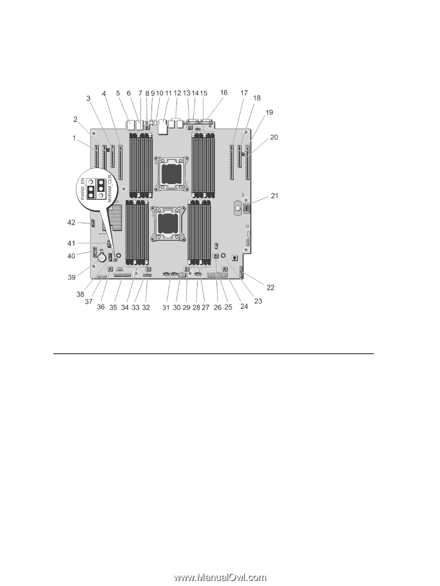
System Board Connectors
Figure 63. System Board Jumpers and Connectors
Item
Connector
Description
1
SLOT1
PCIe card connector 1
2
SLOT2
PCIe card connector 2
3
SLOT3
PCIe card connector 3
4
SLOT4
PCIe card connector 4
5
NIC1
NIC1 connector
6
NIC2
NIC2 connector
7
B1, B5, B9, B2, B6, B10
Memory module sockets
8
FAN1
Cooling shroud fan connector
9
ID_BTN
System identification button
10
CMA_JACK
(Cable management arm) system identification
connector
126