Dell PowerEdge T620 Owner's Manual - Page 83
Removing The Hard-Drive Backplane, 5 inch x4 Dell PowerEdge Express Flash PCIe SSD backplane or - sata ssd system
 |
View all Dell PowerEdge T620 manuals
Add to My Manuals
Save this manual to your list of manuals |
Page 83 highlights
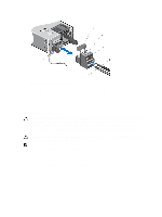
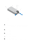
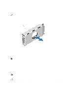
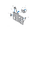
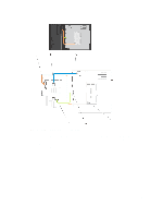
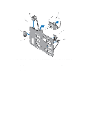
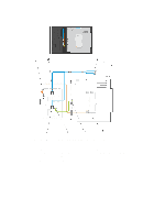
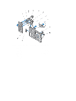
• 2.5 inch x4 Dell PowerEdge Express Flash (PCIe SSD) backplane or • 3.5 inch x12 SAS/SATA backplane or • 2.5 inch x16 SAS/SATA backplane Depending on your configuration, your system supports the following backplane combination: • 3.5 inch x8 SAS/SATA backplane and 2.5 inch x4 PCIe SSD backplane • 2.5 inch x16 SAS/SATA backplane and 2.5 inch x4 PCIe SSD backplane Removing The Hard-Drive Backplane CAUTION: Many repairs may only be done by a certified service technician. You should only perform troubleshooting and simple repairs as authorized in your product documentation, or as directed by the online or telephone service and support team. Damage due to servicing that is not authorized by Dell is not covered by your warranty. Read and follow the safety instructions that came with the product. 1. If installed, remove the front bezel. 2. Turn off the system, including any attached peripherals, and disconnect the system from the electrical outlet. 3. Open the system. CAUTION: To prevent damage to the drives and backplane, you must remove the hard drives from the system before removing the backplane. CAUTION: You must note the number of each hard drive and temporarily label them before removal so that you can replace them in the same locations. 4. Remove the cooling shroud. 5. If applicable, remove the cooling-fan assembly. 6. Remove all hard drives. 7. Disconnect the SAS/SATA/SSD data, signal, and power cable(s) from the backplane. 8. Pull out on the release pin and pull the backplane upward and out from the system. 83
-
 1
1 -
2
-
3
-
4
-
5
-
6
-
7
-
8
-
9
-
10
-
11
-
12
-
13
-
14
-
15
-
16
-
17
-
18
-
19
-
20
-
21
-
22
-
23
-
24
-
25
-
26
-
27
-
28
-
29
-
30
-
31
-
32
-
33
-
34
-
35
-
36
-
37
-
38
-
39
-
40
-
41
-
42
-
43
-
44
-
45
-
46
-
47
-
48
-
49
-
50
-
51
-
52
-
53
-
54
-
55
-
56
-
57
-
58
-
59
-
60
-
61
-
62
-
63
-
64
-
65
-
66
-
67
-
68
-
69
-
70
-
71
-
72
-
73
-
74
-
75
-
76
-
77
-
 78
78 -
 79
79 -
 80
80 -
 81
81 -
 82
82 -
 83
83 -
 84
84 -
 85
85 -
 86
86 -
 87
87 -
 88
88 -
89
-
90
-
91
-
92
-
93
-
94
-
95
-
96
-
97
-
98
-
99
-
100
-
101
-
102
-
103
-
104
-
105
-
106
-
107
-
108
-
109
-
110
-
111
-
112
-
113
-
114
-
115
-
116
-
117
-
118
-
119
-
120
-
121
-
122
-
123
-
124
-
125
-
126
-
127
-
128
-
129
-
130
-
131
-
132
-
133
-
134
-
135
-
136
-
137
-
138
-
139
-
140
-
141
-
142
-
143
-
144
-
145
-
146
-
147
-
148
-
149
 |
 |