Dell PowerEdge T640 EMC PowerEdge T640 Installation and Service Manual - Page 12
Status LED indicators
 |
View all Dell PowerEdge T640 manuals
Add to My Manuals
Save this manual to your list of manuals |
Page 12 highlights
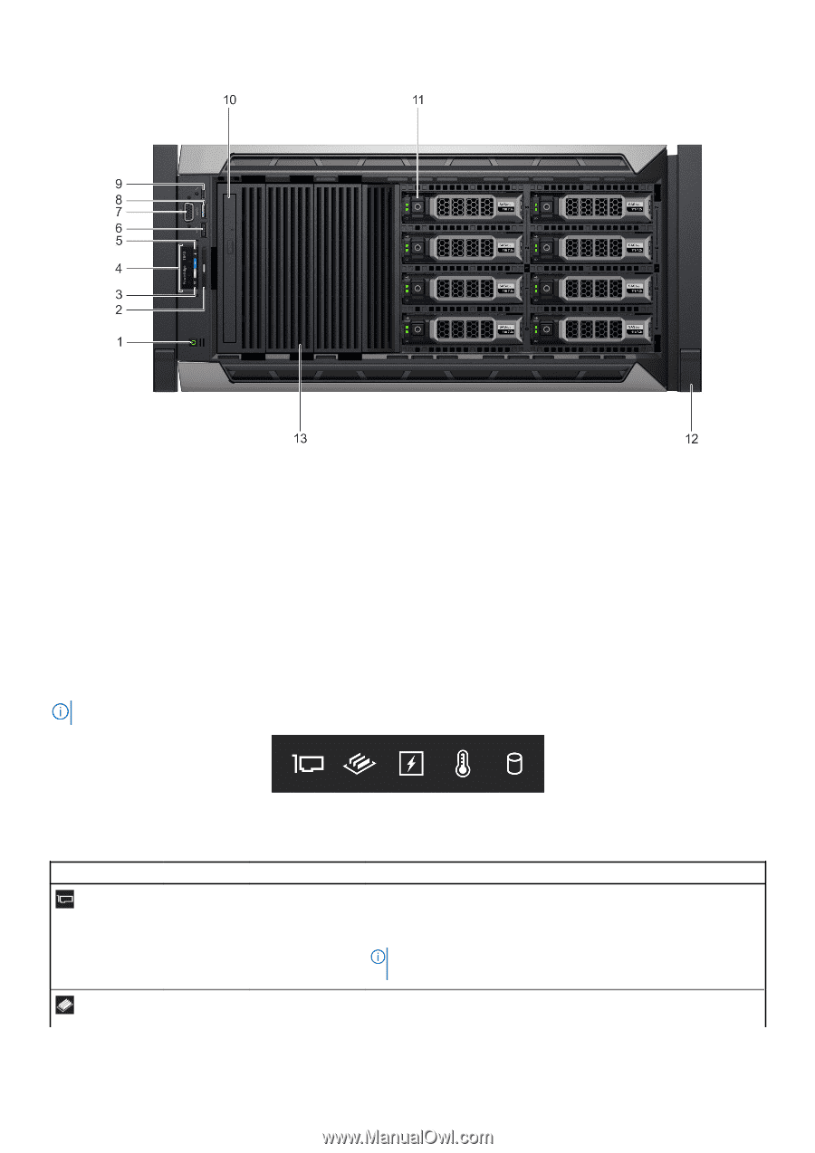
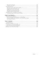
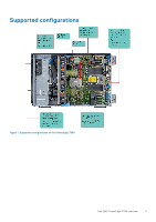
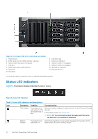
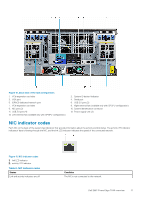
Figure 4. Front view of the 8 x 3.5-inch drive rack system 1. Power button 3. iDRAC Quick Sync 2 wireless indicator (optional) 5. System health and system ID indicator 7. VGA port 9. iDRAC Direct (Micro-AB USB) port 11. Drive slots 13. Drive blank 2. Information tag 4. Status LED indicators 6. USB port (USB 2.0-compliant) 8. USB port (USB 3.0-compliant) 10. Optical drive (optional) 12. Rack ear latch (2) For more information on the ports, see the Technical specifications section. Status LED indicators NOTE: The indicators display solid amber if any error occurs. Figure 5. Status LED indicators Table 1. Status LED indicators and descriptions Icon Description Condition Corrective action PCIe indicator The indicator turns solid amber if a PCIe card experiences an error. Restart the system. Update any required drivers for the PCIe card. Reinstall the card. If the problem persists, see Getting help. NOTE: For more information about the supported PCIe cards, see Expansion card installation guidelines. Memory indicator The indicator turns Check the System Event Log or system messages for the location of the solid amber if a failed memory. Reseat the memory module. 12 Dell EMC PowerEdge T640 overview
-
 1
1 -
2
-
3
-
4
-
5
-
6
-
 7
7 -
 8
8 -
 9
9 -
 10
10 -
 11
11 -
 12
12 -
 13
13 -
 14
14 -
 15
15 -
 16
16 -
 17
17 -
18
-
19
-
20
-
21
-
22
-
23
-
24
-
25
-
26
-
27
-
28
-
29
-
30
-
31
-
32
-
33
-
34
-
35
-
36
-
37
-
38
-
39
-
40
-
41
-
42
-
43
-
44
-
45
-
46
-
47
-
48
-
49
-
50
-
51
-
52
-
53
-
54
-
55
-
56
-
57
-
58
-
59
-
60
-
61
-
62
-
63
-
64
-
65
-
66
-
67
-
68
-
69
-
70
-
71
-
72
-
73
-
74
-
75
-
76
-
77
-
78
-
79
-
80
-
81
-
82
-
83
-
84
-
85
-
86
-
87
-
88
-
89
-
90
-
91
-
92
-
93
-
94
-
95
-
96
-
97
-
98
-
99
-
100
-
101
-
102
-
103
-
104
-
105
-
106
-
107
-
108
-
109
-
110
-
111
-
112
-
113
-
114
-
115
-
116
-
117
-
118
-
119
-
120
-
121
-
122
-
123
-
124
-
125
-
126
-
127
-
128
-
129
-
130
-
131
-
132
-
133
-
134
-
135
-
136
-
137
-
138
-
139
-
140
-
141
-
142
-
143
-
144
-
145
-
146
-
147
-
148
-
149
-
150
-
151
-
152
-
153
-
154
-
155
-
156
-
157
-
158
-
159
-
160
-
161
-
162
-
163
-
164
-
165
 |
 |