Dell PowerEdge T640 EMC PowerEdge T640 Installation and Service Manual - Page 27
Cooling fan matrix, Removing a middle or rear cooling fan
 |
View all Dell PowerEdge T640 manuals
Add to My Manuals
Save this manual to your list of manuals |
Page 27 highlights
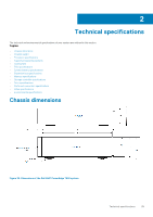
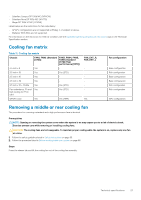
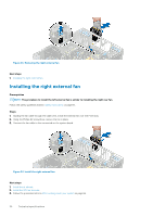
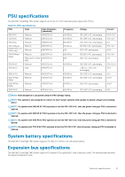
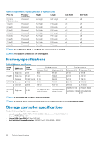
• Solarflare Sunspot DP 10Gb NIC (NPHCM) • Solarflare Nova DP 10Gb NIC (WY7T5) • Qlogic DP 10Gb V1 NIC (VCXN5) Listed below are the restrictions for fan redundancy: • GPGPU configurations are not supported at 35deg. C of ambient or above. • Mellanox 100G NICs are not supported. For information on the restriction for fresh air condition, see the Expanded operating temperature restrictions topic in the Technical Specification section. Cooling fan matrix Table 11. Cooling fan matrix Chassis FAN1, FAN2 (Standard [STD]) FAN3, FAN4, FAN5, FAN6 (Standard [STD]/High performance [HPR]) 3.5 inch x 8 Yes - 3.5 inch x 18 Yes Yes (STD) 2.5 inch x 16 Yes - 2.5 inch x 32 Yes - 2.5 inch x 16 + NVMe Yes Yes (STD) Fan redundancy, FA and Yes high cooling tier PCIe card Yes (STD) GPGPU card Yes Yes (HPR) FAN_EXT_R, FAN_EXT_L - Yes Fan configuration Base configuration Rich configuration Base configuration Base configuration Rich configuration Rich configuration GPU configuration Removing a middle or rear cooling fan The procedure for removing a standard and a high performance fans is identical. Prerequisites NOTE: Opening or removing the system cover when the system is on may expose you to a risk of electric shock. Exercise utmost care while removing or installing cooling fans. CAUTION: The cooling fans are hot swappable. To maintain proper cooling while the system is on, replace only one fan at a time. 1. Follow the safety guidelines listed in Safety instructions on page 65. 2. Follow the procedure listed in Before working inside your system on page 66. Steps Press the release tab and lift the cooling fan out of the cooling fan assembly. Technical specifications 27
-
 1
1 -
2
-
3
-
4
-
5
-
6
-
7
-
8
-
9
-
10
-
11
-
12
-
13
-
14
-
15
-
16
-
17
-
18
-
19
-
20
-
21
-
 22
22 -
 23
23 -
 24
24 -
 25
25 -
 26
26 -
 27
27 -
 28
28 -
 29
29 -
 30
30 -
 31
31 -
 32
32 -
33
-
34
-
35
-
36
-
37
-
38
-
39
-
40
-
41
-
42
-
43
-
44
-
45
-
46
-
47
-
48
-
49
-
50
-
51
-
52
-
53
-
54
-
55
-
56
-
57
-
58
-
59
-
60
-
61
-
62
-
63
-
64
-
65
-
66
-
67
-
68
-
69
-
70
-
71
-
72
-
73
-
74
-
75
-
76
-
77
-
78
-
79
-
80
-
81
-
82
-
83
-
84
-
85
-
86
-
87
-
88
-
89
-
90
-
91
-
92
-
93
-
94
-
95
-
96
-
97
-
98
-
99
-
100
-
101
-
102
-
103
-
104
-
105
-
106
-
107
-
108
-
109
-
110
-
111
-
112
-
113
-
114
-
115
-
116
-
117
-
118
-
119
-
120
-
121
-
122
-
123
-
124
-
125
-
126
-
127
-
128
-
129
-
130
-
131
-
132
-
133
-
134
-
135
-
136
-
137
-
138
-
139
-
140
-
141
-
142
-
143
-
144
-
145
-
146
-
147
-
148
-
149
-
150
-
151
-
152
-
153
-
154
-
155
-
156
-
157
-
158
-
159
-
160
-
161
-
162
-
163
-
164
-
165
 |
 |
