Dell PowerEdge T640 EMC PowerEdge T640 Installation and Service Manual - Page 139
Removing a backplane
 |
View all Dell PowerEdge T640 manuals
Add to My Manuals
Save this manual to your list of manuals |
Page 139 highlights
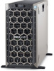
Figure 94. 8 x 3.5 SAS/SATA backplane 1. optical drive power connector [J_ODD1] 3. SAS A0 connector [J_BP_SIG] 5. SAS B0 connector [J_SAS_B0] 2. backplane power connector [J_BP_PWR_A] 4. backplane signal connector [J_SAS_A0] Removing a backplane Prerequisites CAUTION: To prevent damage to the drives and backplane, you must remove the hard drives from the system before removing the backplane. CAUTION: You must note the number of each hard drive and temporarily label them before removal so that you can replace them in the same locations. 1. Follow the safety guidelines listed in Safety instructions on page 65. 2. Follow the procedure listed in Before working inside your system on page 66. 3. Remove all the drives. 4. If installed, remove the middle cooling fan assembly. Steps 1. Disconnect the data, signal, and power cables from the backplane. 2. Pull the release pin and holding the pin, lift the backplane out of the system. Installing and removing system components 139
-
 1
1 -
2
-
3
-
4
-
5
-
6
-
7
-
8
-
9
-
10
-
11
-
12
-
13
-
14
-
15
-
16
-
17
-
18
-
19
-
20
-
21
-
22
-
23
-
24
-
25
-
26
-
27
-
28
-
29
-
30
-
31
-
32
-
33
-
34
-
35
-
36
-
37
-
38
-
39
-
40
-
41
-
42
-
43
-
44
-
45
-
46
-
47
-
48
-
49
-
50
-
51
-
52
-
53
-
54
-
55
-
56
-
57
-
58
-
59
-
60
-
61
-
62
-
63
-
64
-
65
-
66
-
67
-
68
-
69
-
70
-
71
-
72
-
73
-
74
-
75
-
76
-
77
-
78
-
79
-
80
-
81
-
82
-
83
-
84
-
85
-
86
-
87
-
88
-
89
-
90
-
91
-
92
-
93
-
94
-
95
-
96
-
97
-
98
-
99
-
100
-
101
-
102
-
103
-
104
-
105
-
106
-
107
-
108
-
109
-
110
-
111
-
112
-
113
-
114
-
115
-
116
-
117
-
118
-
119
-
120
-
121
-
122
-
123
-
124
-
125
-
126
-
127
-
128
-
129
-
130
-
131
-
132
-
133
-
 134
134 -
 135
135 -
 136
136 -
 137
137 -
 138
138 -
 139
139 -
 140
140 -
 141
141 -
 142
142 -
 143
143 -
 144
144 -
145
-
146
-
147
-
148
-
149
-
150
-
151
-
152
-
153
-
154
-
155
-
156
-
157
-
158
-
159
-
160
-
161
-
162
-
163
-
164
-
165
 |
 |
