Dell Precision 610 Dell Precision WorkStation 610 Mini Tower Systems Service M - Page 13
direction relative to the computer is as shown
 |
View all Dell Precision 610 manuals
Add to My Manuals
Save this manual to your list of manuals |
Page 13 highlights
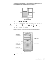
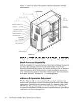
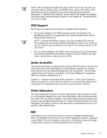
When following the procedures in this manual, assume that the location or direction relative to the computer is as shown in Figure 1-1. top back front bottom Mini Tower Computer Figure 1-2 shows the location of some of the key front-panel features. diskette-drive access indicator reset button hard-disk drive access indicator computer cover release button power button power indicator Mini Tower Computer System Overview 1-3
-
 1
1 -
2
-
3
-
4
-
5
-
6
-
7
-
 8
8 -
 9
9 -
 10
10 -
 11
11 -
 12
12 -
 13
13 -
 14
14 -
 15
15 -
 16
16 -
 17
17 -
 18
18 -
19
-
20
-
21
-
22
-
23
-
24
-
25
-
26
-
27
-
28
-
29
-
30
-
31
-
32
-
33
-
34
-
35
-
36
-
37
-
38
-
39
-
40
-
41
-
42
-
43
-
44
-
45
-
46
-
47
-
48
-
49
-
50
-
51
-
52
-
53
-
54
-
55
-
56
-
57
-
58
-
59
-
60
-
61
-
62
-
63
-
64
-
65
-
66
-
67
-
68
-
69
-
70
-
71
-
72
-
73
-
74
-
75
-
76
-
77
-
78
-
79
-
80
-
81
-
82
-
83
-
84
-
85
-
86
-
87
-
88
-
89
-
90
-
91
-
92
-
93
-
94
-
95
-
96
 |
 |

System Overview
1-3
When following the procedures in this manual, assume that the location or
direction relative to the computer is as shown in Figure 1-1.
Figure 1-2 shows the location of some of the key front-panel features.
front
back
top
bottom
Mini Tower Computer
diskette-drive
access indicator
Mini Tower Computer
power indicator
hard-disk drive
access indicator
power button
reset button
computer cover
release button