Dell Precision 610 Dell Precision WorkStation 610 Mini Tower Systems Service M - Page 89
Xpehuv
 |
View all Dell Precision 610 manuals
Add to My Manuals
Save this manual to your list of manuals |
Page 89 highlights
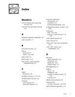
3.5-inch diskette drive assembly removal, 4-12 5.25-inch drive assembly removal, 4-14 advanced expansion subsystem, 1-4 audio controller, 1-7 back-panel features, 1-4 battery removal, 4-27 socket, 1-13, 4-20 beep codes, 3-1 BIOS jumper, 1-15 boot routine, observing when troubleshooting, 2-3 cables DC power, 1-11 CD-ROM connector, 1-13, 4-20 CD-ROM drive removal, 4-14 computer cover removal, 4-3 front panel features, 1-3 computer (continued) internal view, 1-4 orientation, 1-3 technical specifications, 1-18 configuration jumpers, location, 1-13, 4-20 connectors AGP, 1-13, 4-20 location on system board, 1-13, 4-20 control panel removal, 4-9 cover removal, 4-3 key combination, 1-21 key combination, 1-21 DC power cables, illustrated, 1-11 connectors, 1-9 distribution, 1-12 voltage ranges, 1-9 Dell Diagnostics, 2-7 DIMMs about, 1-13 installation, 4-23 location on system board, 1-13, 4-20 removal, 4-23 diskette drive removal, 4-13 diskette drives interface connector, 1-13, 4-20 DMA channel assignments, 1-17 Index 1
-
 1
1 -
2
-
3
-
4
-
5
-
6
-
7
-
8
-
9
-
10
-
11
-
12
-
13
-
14
-
15
-
16
-
17
-
18
-
19
-
20
-
21
-
22
-
23
-
24
-
25
-
26
-
27
-
28
-
29
-
30
-
31
-
32
-
33
-
34
-
35
-
36
-
37
-
38
-
39
-
40
-
41
-
42
-
43
-
44
-
45
-
46
-
47
-
48
-
49
-
50
-
51
-
52
-
53
-
54
-
55
-
56
-
57
-
58
-
59
-
60
-
61
-
62
-
63
-
64
-
65
-
66
-
67
-
68
-
69
-
70
-
71
-
72
-
73
-
74
-
75
-
76
-
77
-
78
-
79
-
80
-
81
-
82
-
83
-
 84
84 -
 85
85 -
 86
86 -
 87
87 -
 88
88 -
 89
89 -
 90
90 -
 91
91 -
 92
92 -
 93
93 -
 94
94 -
95
-
96
 |
 |
