Dell Precision 610 Dell Precision WorkStation 610 Mini Tower Systems Service M - Page 23
sockets can be left between installed DIMMs. However, Dell recommends - ram
 |
View all Dell Precision 610 manuals
Add to My Manuals
Save this manual to your list of manuals |
Page 23 highlights
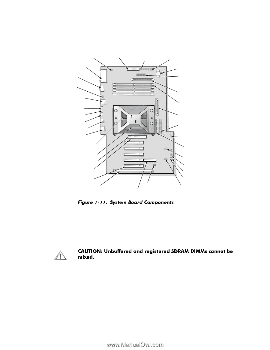
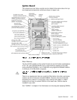
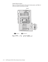
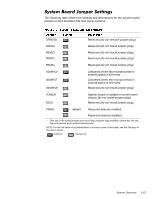
The subsections that follow provide service-related information about the system board and components, which are shown in Figure 1-11. CD-ROM drive audio interface connector (CD-IN) parallel/SCSI port connectors (PARALLEL/SCSI) (stacked) serial port connectors (SERIAL 1/2) (stacked) processor fan connector (FAN) main power input connector (POWER1) SPREAD jumper diskette-drive interface connector (DISK2) battery socket (BATTERY) secondary diskette-drive interface connector (DISKETTE) (pin-1 corner) mouse/keyboard connectors (MOUSE/KYBD) (stacked) secondary SCSI connector (SCSI_NARROW) microphone jack (MIC-IN) DIMM sockets (DIMM_A-DIMM_D) line-out jack (LINE-OUT) line-in jack (LINE-IN) USB connectors (USB) primary SCSI connector front of (SCSI_ULTRA2) computer primary EIDE interface connector (IDE1) (pin-1 corner) NIC connector (ENET) primary Slot 2 SEC cartridge connector (SLOT2_PRI) secondary Slot 2 SEC cartridge connector (SLOT2_SEC) AGP expansion-card connector (AGP) CPU mismatch LED PCI expansion-card connectors (PCI1-PCI5) control panel connector (PANEL) secondary EIDE interface connector (IDE2) (pin-1 corner) modem connector (MODEM_IN) configuration jumpers power LED standby LED ISA expansion-card connector (ISA1) RAID connector (RAID) Wakeup On LAN hard-disk drive access indicator card connector (LAN) connector (AUX LED) The four DIMM sockets on the system board can accommodate combinations of 32-, 64-, and 128-MB DIMMs up to a total memory capacity of 512 MB using unbuffered SDRAM or up to 2048 MB using registered SDRAM DIMMs. A minimum of 64 MB RAM is required. There is no requirement that one socket be filled before the other, and empty sockets can be left between installed DIMMs. However, Dell recommends populating the sockets in consecutive order starting with DIMM A. DIMM sockets do not have to contain DIMMs of the same size. DIMMs may be installed in any order. See "DIMMs" in Chapter 4 for information on removing and replacing DIMMs. System Overview 1-13
-
 1
1 -
2
-
3
-
4
-
5
-
6
-
7
-
8
-
9
-
10
-
11
-
12
-
13
-
14
-
15
-
16
-
17
-
 18
18 -
 19
19 -
 20
20 -
 21
21 -
 22
22 -
 23
23 -
 24
24 -
 25
25 -
 26
26 -
 27
27 -
 28
28 -
29
-
30
-
31
-
32
-
33
-
34
-
35
-
36
-
37
-
38
-
39
-
40
-
41
-
42
-
43
-
44
-
45
-
46
-
47
-
48
-
49
-
50
-
51
-
52
-
53
-
54
-
55
-
56
-
57
-
58
-
59
-
60
-
61
-
62
-
63
-
64
-
65
-
66
-
67
-
68
-
69
-
70
-
71
-
72
-
73
-
74
-
75
-
76
-
77
-
78
-
79
-
80
-
81
-
82
-
83
-
84
-
85
-
86
-
87
-
88
-
89
-
90
-
91
-
92
-
93
-
94
-
95
-
96
 |
 |