Dell Vostro 5390 Service Manual
Dell Vostro 5390 Manual
 |
View all Dell Vostro 5390 manuals
Add to My Manuals
Save this manual to your list of manuals |
Dell Vostro 5390 manual content summary:
- Dell Vostro 5390 | Service Manual - Page 1
Dell Vostro 5390 Service Manual Regulatory Model: P114G Regulatory Type: P114G001 - Dell Vostro 5390 | Service Manual - Page 2
of data and tells you how to avoid the problem. WARNING: A WARNING indicates a potential for property damage, personal injury, or death. © 2019 Dell Inc. or its subsidiaries. All rights reserved. Dell, EMC, and other trademarks are trademarks of Dell Inc. or its subsidiaries. Other trademarks may be - Dell Vostro 5390 | Service Manual - Page 3
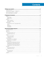
1 Working on your computer...6 Safety instructions...6 Turning off your computer - Windows 10...6 Before working inside your computer...6 After working inside your computer...7 2 Technology and components...8 DDR4...8 DDR4 Details...8 Memory Errors...9 HDMI 1.4...9 HDMI 1.4 Features...9 Advantages - Dell Vostro 5390 | Service Manual - Page 4
Removing the speakers...27 Installing the speakers...28 WLAN card...29 Removing the WLAN card...29 Installing the WLAN card...30 WWAN card...31 Removing the WWAN card...31 Installing the WWAN card...32 Touchpad...33 Removing the touchpad...33 Installing the touchpad...34 Power-adapter port...35 - Dell Vostro 5390 | Service Manual - Page 5
palm-rest and keyboard assembly 63 Installing the palm-rest and keyboard assembly...64 4 Troubleshooting...66 Enhanced Pre-Boot System Assessment (ePSA) diagnostics 66 Running the ePSA diagnostics...66 power cycle...68 Flea power release...68 5 Getting help...69 Contacting Dell...69 Contents 5 - Dell Vostro 5390 | Service Manual - Page 6
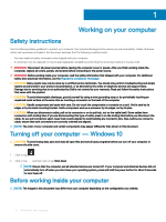
only perform troubleshooting and simple repairs as authorized in your product documentation, or as directed by the online or telephone service and support team. Damage due to servicing that is not authorized by Dell is not covered by your warranty. Read and follow the safety instructions that came - Dell Vostro 5390 | Service Manual - Page 7
After working inside your computer CAUTION: Leaving stray or loose screws inside your computer may severely damage your computer. 1 Replace all screws and ensure that no stray screws remain inside your computer. 2 Connect any external devices, peripherals, or cables you removed before working on - Dell Vostro 5390 | Service Manual - Page 8
1.2 volts, compared to DDR3 which requires 1.5 volts of electrical power to operate. DDR4 also supports a new, deep power-down mode that allows the host device to go into standby without needing to refresh its memory. Deep power-down mode is expected to reduce standby power consumption by 40 to 50 - Dell Vostro 5390 | Service Manual - Page 9
If all memory fails, the LCD does not turn on. Troubleshoot for possible memory failure by trying known good memory modules in the memory connectors on advantage is cable reduction and content protection provisions. HDMI supports standard, enhanced, or high-definition video, plus multichannel - Dell Vostro 5390 | Service Manual - Page 10
connection between host computers and peripheral devices like mice, keyboards, external drivers, and printers. Let's take a quick look on the USB evolution devices • New power management features • Full-duplex data transfers and support for new transfer types • Backward USB 2.0 compatibility • New - Dell Vostro 5390 | Service Manual - Page 11
Speed Currently, there are 3 speed modes defined by the latest USB 3.0/USB 3.1 Gen 1 specification. They are Super-Speed, Hi-Speed and FullSpeed. The new SuperSpeed mode has a transfer rate of 4.8Gbps. While the specification retains Hi-Speed, and Full-Speed USB mode, commonly known as USB 2.0 and - Dell Vostro 5390 | Service Manual - Page 12
contact when connected to a proper SuperSpeed USB connection. Windows 10 will be bringing native support for USB 3.1 Gen 1 controllers. This is in contrast to previous versions of Windows, which continue to require separate drivers for USB 3.0/USB 3.1 Gen 1 controllers. 12 Technology and components - Dell Vostro 5390 | Service Manual - Page 13
procedures in this document require the following tools: • Phillips #0 screwdriver • Phillips #1 screwdriver • Plastic scribe NOTE: The #0 screw driver is for screws 0-1 and the #1 screw driver is for screws 2-4 Screw list The table provides the list of screws that are used for securing different - Dell Vostro 5390 | Service Manual - Page 14
1 Loosen the three captive screws on the base cover. 2 Remove the four screws (M2x6) that secure the base cover to the palm-rest and keyboard assembly. 3 Pry the base cover starting from the top-left corner of the palm-rest and keyboard assembly. 4 Lift the base cover off the palm-rest and keyboard - Dell Vostro 5390 | Service Manual - Page 15
that secure the base cover to the palm-rest and keyboard assembly. 1 Follow the procedure in After working inside your computer. Battery Removing the battery 1 Follow the procedure in Before working inside your computer. 2 Remove the base cover. The following image indicates the location of the - Dell Vostro 5390 | Service Manual - Page 16
and keyboard assembly. 3 Remove the screw (M1.6x4) that secures the battery to the system board and palm-rest and keyboard assembly. 4 Lift the battery off the palm-rest and keyboard assembly. Installing the battery If you are replacing a component, remove the existing component before performing - Dell Vostro 5390 | Service Manual - Page 17
cover. 2 Follow the procedure in After working inside your computer. Coin-cell battery Removing the coin-cell battery 1 Follow the procedure in Before working inside your computer. CAUTION: Removing the coin-cell battery resets the BIOS setup program's settings to default. It is recommended that you - Dell Vostro 5390 | Service Manual - Page 18
from the system board. 2 Remove the coin-cell battery cable from the routing guide. 3 Peel the coin-cell battery off the palm-rest and keyboard assembly. Installing the coin-cell battery If you are replacing a component, remove the existing component before performing the installation procedure - Dell Vostro 5390 | Service Manual - Page 19
to the slot on the palm-rest and keyboard assembly. 2 Route the coin-cell battery cable through the routing guide. 3 Connect the coin-cell battery cable to the system board. 1 Install the battery. 2 Install the base cover. 3 Follow the procedure in After working inside your computer. Solid-state - Dell Vostro 5390 | Service Manual - Page 20
1 Remove the screw (M2x2.5) that secures the solid-state drive to the system board. 2 Slide and remove the solid-state drive off the solid-state drive slot on the system board. Installing the M.2 2280 solid-state drive If you are replacing a component, remove the existing component before performing - Dell Vostro 5390 | Service Manual - Page 21
-state drive slot on the system board. 2 Replace the screw (M2x2.5) that secures the solid-state drive to the system board. 1 Install the battery. 2 Install the base cover. 3 Follow the procedure in After working inside your computer. Removing the M.2 2230 solid-state drive 1 Follow the procedure in - Dell Vostro 5390 | Service Manual - Page 22
1 Remove the screw (M2x2.5) that secures the solid-state drive bracket to the system board. 2 Slide and remove the solid-state drive bracket off the solid-state drive on the system board. 3 Slide and remove the solid-state drive off the solid-state drive slot on the system board. Installing the M.2 - Dell Vostro 5390 | Service Manual - Page 23
to the solid-state drive on the system board. 3 Replace the screw (M2x2.5) that secures the solid-state drive to the system board. 1 Install the battery. 2 Install the base cover. 3 Follow the procedure in After working inside your computer. Heat sink Removing the heat sink 1 Follow the procedure in - Dell Vostro 5390 | Service Manual - Page 24
1 Peel the tape that secures the heat sink to the system board. 2 In the reverse sequential order (7>6>5>4>3>2>1), loosen the seven captive screws that secure the heat sink to the system board. 3 Lift the heat sink off the system board. Installing the heat sink If you are replacing a component, - Dell Vostro 5390 | Service Manual - Page 25
screws that secure the heat sink to the system board. 3 Adhere the tape that secures the heat sink to the system board. 1 Install the battery. 2 Install the base cover. 3 Follow the procedure in After working inside your computer. Fan Removing the fan 1 Follow the procedure in Before working inside - Dell Vostro 5390 | Service Manual - Page 26
1 Disconnect the I/O-board cable from the system board and I/O board. NOTE: This step is only applicable for computers shipped with a WWAN configuration. 2 Remove the two (M2x3) screws that secure the fan to the system board. 3 Lift the fan slightly off the palm-rest and keyboard assembly. 4 - Dell Vostro 5390 | Service Manual - Page 27
board cable to the system board and I/O board. NOTE: This step is only applicable for computers shipped with a WWAN configuration. 1 Install the battery. 2 Install the base cover. 3 Follow the procedure in After working inside your computer. Speakers Removing the speakers 1 Follow the procedure in - Dell Vostro 5390 | Service Manual - Page 28
3 Remove the battery. The following image indicates the location of speakers and provides assembly. 4 Note the routing of the speaker cable and remove the speaker cable from the routing guides on the palm-rest and keyboard assembly. NOTE: Note the position of the rubber grommets before lifting - Dell Vostro 5390 | Service Manual - Page 29
-rest and keyboard assembly. 2 Route the speaker cable through the routing guides on the palm-rest and keyboard assembly. 3 Adhere the tapes that the system board and close the latch to secure the cable. 1 Install the battery. 2 Install the base cover. 3 Follow the procedure in After working inside - Dell Vostro 5390 | Service Manual - Page 30
The following image indicates the location of WLAN card and provides a visual representation of the removal procedure. 1 Remove the screw (M2x2.5) that secures the WLAN-card bracket to the WLAN card and lift the WLAN-card bracket off the WLAN card. 2 Disconnect the antenna cables from the WLAN card. - Dell Vostro 5390 | Service Manual - Page 31
place the WLAN card bracket on the WLAN card. 4 Replace the screw (M2x2.5) to secure the WLAN card bracket to the WLAN card. 1 Install the battery. 2 Install the base cover. 3 Follow the procedure in After working inside your computer. WWAN card Removing the WWAN card NOTE: This procedure is only - Dell Vostro 5390 | Service Manual - Page 32
1 Remove the screw (M2x2.5) that secures the WWAN card bracket to the WWAN card. 2 Note the alignment of the WWAN-card bracket before lifting it off the WWAN card. 3 Disconnect the antenna cables from the WWAN card. 4 Slide and remove the WWAN card from the WWAN card slot. Installing the WWAN card - Dell Vostro 5390 | Service Manual - Page 33
the WWAN-card bracket on the WWAN card. 3 Replace the screw (M2x2.5) that secures the WWAN bracket to the WWAN card. 1 Install the battery. 2 Install the base cover. 3 Follow the procedure in After working inside your computer. Touchpad Removing the touchpad 1 Follow the procedure in Before working - Dell Vostro 5390 | Service Manual - Page 34
1 Peel the tapes that secure the touchpad to the palm-rest and keyboard assembly. 2 Open the latch and disconnect the touchpad cable from the system board. 3 Remove the three (M1.6x2) screws that secure the touchpad bracket to the palm-rest and keyboard assembly. 4 Lift the touchpad bracket off the - Dell Vostro 5390 | Service Manual - Page 35
and close the latch to secure the cable. 6 Adhere the tape that secures the touchpad to the palm-rest and keyboard assembly. 1 Install the battery. 2 Install the base cover. 3 Follow the procedure in After working inside your computer. Power-adapter port Removing the power-adapter port 1 Follow the - Dell Vostro 5390 | Service Manual - Page 36
2 Remove the base cover. 3 Remove the battery. The following image indicates the location of power-adapter port and provides a visual representation of the removal procedure. 1 Remove the screw (M2.5x3.5) that secures - Dell Vostro 5390 | Service Manual - Page 37
alignment posts, close the display hinges. 6 Replace the screw (M2x4) that secure the right display hinge to the system board. 1 Install the battery. 2 Install the base cover. 3 Follow the procedure in After working inside your computer. Display assembly Removing the display assembly 1 Follow the - Dell Vostro 5390 | Service Manual - Page 38
38 Removing and installing components - Dell Vostro 5390 | Service Manual - Page 39
1 Remove the screw (M2.5x3.5) that secures the display-cable bracket to the system board. 2 Lift the display-cable bracket off the system board. 3 Using the pull tab, disconnect the display cable from the system board. 4 Remove the two screws (M2.5x3.5) that secure the left display hinge to the I/O - Dell Vostro 5390 | Service Manual - Page 40
Installing the display assembly If you are replacing a component, remove the existing component before performing the installation procedure. The following image indicates the location of display assembly and provides a visual representation of the installation procedure. 40 Removing and installing - Dell Vostro 5390 | Service Manual - Page 41
the display-cable bracket on the display cable. 7 Replace the screw (M2x4) that secures the display-cable bracket to the system board. 1 Install the battery. 2 Install the base cover. 3 Follow the procedure in After working inside your computer. I/O board Removing and installing components 41 - Dell Vostro 5390 | Service Manual - Page 42
Removing the I/O board 1 Follow the procedure in Before working inside your computer. 2 Remove the base cover. 3 Remove the battery. 4 Remove the fan. The following image indicates the location of I/O board and provides a visual representation of the removal procedure. 1 Remove the two screws (M2. - Dell Vostro 5390 | Service Manual - Page 43
the two screws (M2.5x3.5) that secure the left display hinge to the I/O board and palm-rest and keyboard assembly. 1 Install the fan. 2 Install the battery. Removing and installing components 43 - Dell Vostro 5390 | Service Manual - Page 44
. Power-button board Removing the power-button board 1 Follow the procedure in Before working inside your computer. 2 Remove the base cover. 3 Remove the battery. 4 Remove the WLAN card. 5 Remove the fan. 6 Remove the I/O board. The following image indicates the location of power button and provides - Dell Vostro 5390 | Service Manual - Page 45
for computers shipped with a fingerprint reader. 1 Follow the procedure in Before working inside your computer. 2 Remove the base cover. 3 Remove the battery. 4 Remove the WLAN card. 5 Remove the fan. 6 Remove the I/O board. The following image indicates the location of power button with fingerprint - Dell Vostro 5390 | Service Manual - Page 46
1 Remove the screw (M1.6x2) that secures the power-button bracket to the palm-rest and keyboard assembly. 2 Remove the screw (M1.6x2) that secures the power button with fingerprint reader to the palm-rest and keyboard assembly. 3 Open the latch and disconnect the fingerprint-reader cable from the - Dell Vostro 5390 | Service Manual - Page 47
-button bracket to the palm-rest and keyboard assembly. 1 Install the I/O board. 2 Install the fan. 3 Install the WLAN card. 4 Install the battery. 5 Install the base cover. 6 Follow the procedure in After working inside your computer. System board Removing the system board 1 Follow the procedure in - Dell Vostro 5390 | Service Manual - Page 48
keyboard cable from the system board. 10 Open the latch and disconnect the keyboard backlit cable from the system board. 11 Disconnect the coin-cell battery cable from the system board. 12 Disconnect the power-adapter port cable from the system board. 13 Using the pull tab, disconnect the display - Dell Vostro 5390 | Service Manual - Page 49
the display cable on to the connector on the system board6 3 Connect the power-adapter port cable to the system board. 4 Connect the coin-cell battery cable to the system board. 5 Connect the keyboard backlit cable to the system board and close the latch to secure the cable. 6 Connect the keyboard - Dell Vostro 5390 | Service Manual - Page 50
the fan. 5 Install the WLAN card. 6 Install the M.2 2280 solid-state drive or M.2 2230 solid-state drive, whichever applicable. 7 Install the battery. 8 Install the base cover. 9 Follow the procedure in After working inside your computer. Display bezel Removing the display bezel NOTE: This procedure - Dell Vostro 5390 | Service Manual - Page 51
1 Carefully pry the edges of the display bezel off the display back-cover and antenna assembly. 2 Remove the display bezel off the display back-cover and antenna assembly. Installing the display bezel NOTE: This procedure is not applicable to computers shipped with a WWAN configuration. If you are - Dell Vostro 5390 | Service Manual - Page 52
to computers shipped with a WWAN configuration. 1 Follow the procedure in Before working inside your computer. 2 Remove the base cover. 3 Remove the battery. 4 Remove the WLAN card. 5 Remove the display assembly. 6 Remove the display bezel. The following image indicates the location of display panel - Dell Vostro 5390 | Service Manual - Page 53
Removing and installing components 53 - Dell Vostro 5390 | Service Manual - Page 54
1 Using a plastic scribe, slide out the pull tab of the SR tape from both sides of the display panel. 2 Pull out a small section of the SR tape. 3 Roll the SR tape around the plastic scribe. NOTE: To avoid severing/breaking the SR tape, pull out only a small section of the SR tape and then roll the - Dell Vostro 5390 | Service Manual - Page 55
Installing the display panel NOTE: This procedure is not applicable to computers shipped with a WWAN configuration. If you are replacing a component, remove the existing component before performing the installation procedure. The following image indicates the location of display panel and provides a - Dell Vostro 5390 | Service Manual - Page 56
1 Peel off the transparent protective films from the SR tapes. 2 Align and adhere both the SR tapes to the plastic edge of the display back-cover. 3 Peel off the blue protective films from the SR tapes. 4 Starting from the top, align and place the display panel on the display back-cover. 5 Remove - Dell Vostro 5390 | Service Manual - Page 57
computers shipped with a WWAN configuration. 1 Follow the procedure in Before working inside your computer. 2 Remove the base cover. 3 Remove the battery. 4 Remove the WLAN card. 5 Remove the display assembly. 6 Remove the display bezel. The following image indicates the location of display hinges - Dell Vostro 5390 | Service Manual - Page 58
the display hinges to the display back-cover. 1 Install the display bezel. 2 Install the display assembly. 3 Install the WLAN card. 4 Install the battery. 5 Install the base cover. 6 Follow the procedure in After working inside your computer. Camera Removing the camera NOTE: This procedure is not - Dell Vostro 5390 | Service Manual - Page 59
3 Remove the battery. 4 Remove the WLAN card. 5 Remove the display assembly. 6 Remove the display bezel. 7 Remove the display panel. The following image indicates the location of camera and - Dell Vostro 5390 | Service Manual - Page 60
the display back-cover. 1 Install the display panel. 2 Install the display bezel. 3 Install the display assembly. 4 Install the WLAN card. 5 Install the battery. 6 Install the base cover. 7 Follow the procedure in After working inside your computer. Display back-cover Removing the display back-cover - Dell Vostro 5390 | Service Manual - Page 61
The following image indicates the display back-cover and provides a visual representation of the removal procedure. After performing all the prerequisites, we are left with the display back-cover. NOTE: Antenna cables are a part of the palm-rest and keyboard assembly for computers shipping with - Dell Vostro 5390 | Service Manual - Page 62
the display panel. 4 Install the display hinges. 5 Install the display bezel. 6 Install the display assembly. 7 Install the WLAN card. 8 Install the battery. 9 Install the base cover. 10 Follow the procedure in After working inside your computer. Display cable Removing the display cable NOTE: This - Dell Vostro 5390 | Service Manual - Page 63
display cable to the display back-cover. 1 Install the display bezel. 2 Install the display panel. 3 Install the display assembly. 4 Install the battery. 5 Install the base cover. 6 Follow the procedure in After working inside your computer. Palm-rest and keyboard assembly Removing the palm-rest - Dell Vostro 5390 | Service Manual - Page 64
5 Remove the speakers. 6 Remove the system board. 7 Remove the display assembly. 8 Remove the power button with fingerprint reader or power-button board, whichever applicable. 9 Remove the power-adapter port. 10 Remove the touchpad. The following image indicates the palm-rest and keyboard assembly - Dell Vostro 5390 | Service Manual - Page 65
-button board, whichever applicable. 4 Install the display assembly. 5 Install the system board. 6 Install the speakers. 7 Install the WLAN card. 8 Install the battery. 9 Install the base cover. 10 Follow the procedure in After working inside your computer. Removing and installing components 65 - Dell Vostro 5390 | Service Manual - Page 66
the device from the left pane and click Run Tests. 8 If there are any issues, error codes are displayed. Note the error code and validation number and contact Dell. System diagnostic lights Battery-status light Indicates the power and battery-charge status. Solid white - Power adapter is connected - Dell Vostro 5390 | Service Manual - Page 67
3,5 3,6 3,7 Problem description Processor failure System board: BIOS or ROM (Read-Only Memory) failure No memory or RAM (Random-Access Memory) detected Memory or RAM (Random-Access Memory) failure Invalid memory installed System-board or chipset error Display failure Coin-cell battery failure PCI - Dell Vostro 5390 | Service Manual - Page 68
Turn on your computer. 2 Go to www.dell.com/support. 3 Click Product support, enter the Service Tag of your computer, and then click Submit. NOTE: If you do not have the Service Tag, use the auto-detect feature or manually browse for your computer model. 4 Click Drivers & downloads > Find it myself - Dell Vostro 5390 | Service Manual - Page 69
options. Availability varies by country and product, and some services may not be available in your area. To contact Dell for sales, technical support, or customer service issues: 1 Go to Dell.com/support. 2 Select your support category. 3 Verify your country or region in the Choose a Country
-
 1
1 -
 2
2 -
 3
3 -
 4
4 -
 5
5 -
 6
6 -
 7
7 -
8
-
9
-
10
-
11
-
12
-
13
-
14
-
15
-
16
-
17
-
18
-
19
-
20
-
21
-
22
-
23
-
24
-
25
-
26
-
27
-
28
-
29
-
30
-
31
-
32
-
33
-
34
-
35
-
36
-
37
-
38
-
39
-
40
-
41
-
42
-
43
-
44
-
45
-
46
-
47
-
48
-
49
-
50
-
51
-
52
-
53
-
54
-
55
-
56
-
57
-
58
-
59
-
60
-
61
-
62
-
63
-
64
-
65
-
66
-
67
-
68
-
69
 |
 |

Dell Vostro 5390
Service Manual
Regulatory Model: P114G
Regulatory Type: P114G001