Epson ActionPrinter 3000 User Manual - Page 99
connection on the return side., twisted-pair cable for each signal and to complete
 |
View all Epson ActionPrinter 3000 manuals
Add to My Manuals
Save this manual to your list of manuals |
Page 99 highlights
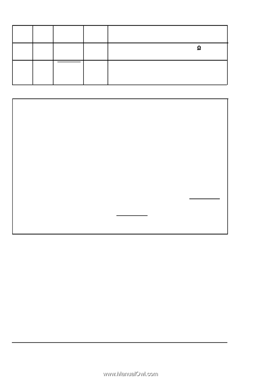
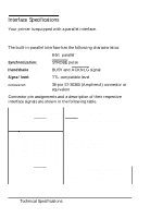
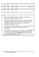
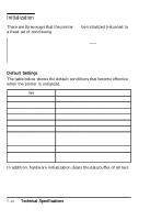
Interface Specifications Signal Return Pin Pin Signal Direction Description 35 - - OUT Pulled up to +5 V through 3.3 K resistance. 36 - SLCT IN IN Internal fixing can be carried out with Jumper J6. The level of this signal is factory-set to LOW. Note: l The column heading "Direction" refers to the direction of signal flow as viewed from the printer. l "Return" denotes the twisted-pair return, to be connected at signal ground level. For the interface wiring, be sure to use a twisted-pair cable for each signal and to complete the connection on the return side. l All interface conditions are based on TTL level. Both the rise and fall times of each signal must be less than 0.2 microseconds. l Data transfer must be carried out by observing the ACKNLG or BUSY signal. (Data transfer to this printer can be carried out only after receipt of the ACKNLG signal or when the level of the BUSY signal is LOW.) 7-10 Technical Specifications
-
 1
1 -
2
-
3
-
4
-
5
-
6
-
7
-
8
-
9
-
10
-
11
-
12
-
13
-
14
-
15
-
16
-
17
-
18
-
19
-
20
-
21
-
22
-
23
-
24
-
25
-
26
-
27
-
28
-
29
-
30
-
31
-
32
-
33
-
34
-
35
-
36
-
37
-
38
-
39
-
40
-
41
-
42
-
43
-
44
-
45
-
46
-
47
-
48
-
49
-
50
-
51
-
52
-
53
-
54
-
55
-
56
-
57
-
58
-
59
-
60
-
61
-
62
-
63
-
64
-
65
-
66
-
67
-
68
-
69
-
70
-
71
-
72
-
73
-
74
-
75
-
76
-
77
-
78
-
79
-
80
-
81
-
82
-
83
-
84
-
85
-
86
-
87
-
88
-
89
-
90
-
91
-
92
-
93
-
 94
94 -
 95
95 -
 96
96 -
 97
97 -
 98
98 -
 99
99 -
 100
100 -
 101
101 -
 102
102 -
 103
103 -
 104
104 -
105
-
106
-
107
-
108
-
109
-
110
-
111
-
112
-
113
-
114
-
115
-
116
-
117
-
118
-
119
-
120
-
121
-
122
-
123
-
124
-
125
 |
 |