Epson LX-90 User Manual - IBM PC Jr. 8690 PIC for LX-90 - Page 60
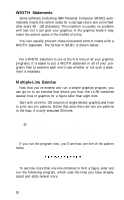
Because IBM Personal Computer BASIC will not send CHR$26, of each column.
 |
View all Epson LX-90 manuals
Add to My Manuals
Save this manual to your list of manuals |
Page 60 highlights
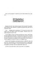
lines, but no dots can overlap. In low-speed double density dots can be placed on vertical lines and they can overlap. Now look at the figure designed for high-speed double density. It should point you in the right direction for your own designs. Figure 8-4. Arrow design After plotting all the dots as in Figure 8-4, you calculate the numbers for each pin pattern by dividing the design grid into separate print lines. For the arrow design, the grid was divided into three lines, each seven dots high. Then each column was examined and the sums of the pin values determined. This process for the first line is shown in Figure 8-5. The pin values are on the left side and the sums are at the bottom of each column. Because IBM Personal Computer BASIC will not send CHR$(26), do not use that number in any of your graphics programs. Those of you who have read the previous chapter will see that designing graphics is much like designing user-defined characters. 55
-
 1
1 -
2
-
3
-
4
-
5
-
6
-
7
-
8
-
9
-
10
-
11
-
12
-
13
-
14
-
15
-
16
-
17
-
18
-
19
-
20
-
21
-
22
-
23
-
24
-
25
-
26
-
27
-
28
-
29
-
30
-
31
-
32
-
33
-
34
-
35
-
36
-
37
-
38
-
39
-
40
-
41
-
42
-
43
-
44
-
45
-
46
-
47
-
48
-
49
-
50
-
51
-
52
-
53
-
54
-
 55
55 -
 56
56 -
 57
57 -
 58
58 -
 59
59 -
 60
60 -
 61
61 -
 62
62 -
 63
63 -
 64
64 -
 65
65 -
66
-
67
-
68
-
69
-
70
-
71
-
72
-
73
-
74
-
75
-
76
-
77
-
78
-
79
-
80
-
81
-
82
-
83
-
84
-
85
-
86
-
87
-
88
-
89
-
90
-
91
-
92
-
93
-
94
-
95
-
96
-
97
-
98
-
99
-
100
 |
 |
