Fujitsu MAN3367FC Manual/User Guide - Page 139
Index
 |
View all Fujitsu MAN3367FC manuals
Add to My Manuals
Save this manual to your list of manuals |
Page 139 highlights
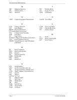
Index 1-1x-xx 7-4 +12 VDC 4-7 3-0C-03 7-3 3-1x-xx 7-4 32/34 RLL decoding circuit 8-9 4-40-xx 7-4 4-C4-xx 7-4 5-2x-xx 7-4 5-3D-00 7-4 5-90-00 7-4 A AC noise filter 4-8 activation 8-12 actuator 1-6, 8-2 ADC 8-9 AGC amplifier 8-9 air circulation (recirculation filter,breather filter) 1-6 air filter 8-2 allowable input voltage and current 4-7 alternate area 3-11 alternate block allocation 3-11 by FORMAT UNIT command 3-13 by REASSIGN BLOCKS command 3-14 during FORMAT UNIT command execution 3-12 alternate cylinder 3-5 alternate spare area 3-4 analog filter 8-9 automatic alternate block allocation 3-15 at read operation 3-15 at write operation 3-15 automatic alternate block reassignment 1-4 B B-47-xx 7-4 B-49-00 7-4 B-4D-xx 7-4 B-4E-00 7-4 basic operation test 6-5 BCRC 3-9 block address of user space 3-10 block descriptor 5-10 block diagram of read-write circuit 8-8 of servo control circuit 8-10 C caching parameter 5-15 changing revision number in field 6-9 checking at abnormal end 5-10 connection 5-7 IDD connection 5-8, 5-9 initial operation 5-6 operation after installation and preparing IDD for use 5-6 procedure 5-7 circuit configuration 8-3, 8-4 command queuing feature 1-3 compactness 1-2 connection requirement 4-9 connector 4-9 continuous block processing 1-2 controller circuit 1-7, 8-3 control mode parameter 5-15 cylinder configuration 3-1 D data field 3-8 data format 3-1 data security at power failure 2-7 data space 3-1 data zone 8-11 dead space 8-11 defective block slipping 1-4 defect list 3-11 defect management 3-11 definition of sense data 7-3 delivery 5-2 diagnosis 1-4 diagnostics 6-1 and maintenance 6-1 diagnostic test 6-12 disconnection/reconnection parameter 5-14 disk 1-5, 8-2 disk drive configuration 8-1 replacement 6-8 troubleshooting 6-15 disk/head configuration 1-6 disk read error 7-4 dismounting drive 5-5 dual-port support 1-2 C141-E133-02EN IN-1
-
 1
1 -
2
-
3
-
4
-
5
-
6
-
7
-
8
-
9
-
10
-
11
-
12
-
13
-
14
-
15
-
16
-
17
-
18
-
19
-
20
-
21
-
22
-
23
-
24
-
25
-
26
-
27
-
28
-
29
-
30
-
31
-
32
-
33
-
34
-
35
-
36
-
37
-
38
-
39
-
40
-
41
-
42
-
43
-
44
-
45
-
46
-
47
-
48
-
49
-
50
-
51
-
52
-
53
-
54
-
55
-
56
-
57
-
58
-
59
-
60
-
61
-
62
-
63
-
64
-
65
-
66
-
67
-
68
-
69
-
70
-
71
-
72
-
73
-
74
-
75
-
76
-
77
-
78
-
79
-
80
-
81
-
82
-
83
-
84
-
85
-
86
-
87
-
88
-
89
-
90
-
91
-
92
-
93
-
94
-
95
-
96
-
97
-
98
-
99
-
100
-
101
-
102
-
103
-
104
-
105
-
106
-
107
-
108
-
109
-
110
-
111
-
112
-
113
-
114
-
115
-
116
-
117
-
118
-
119
-
120
-
121
-
122
-
123
-
124
-
125
-
126
-
127
-
128
-
129
-
130
-
131
-
132
-
133
-
 134
134 -
 135
135 -
 136
136 -
 137
137 -
 138
138 -
 139
139 -
 140
140 -
 141
141 -
 142
142 -
 143
143 -
 144
144 -
145
-
146
-
147
-
148
 |
 |
