Fujitsu MAN3367FC Manual/User Guide - Page 65
Connection Requirements
 |
View all Fujitsu MAN3367FC manuals
Add to My Manuals
Save this manual to your list of manuals |
Page 65 highlights
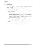
4.3 Connection Requirements 4.3.1 Connector Figure 4.9 shows the locations of interface connector. 4.3 Connection Requirements Interface connector (CN1) (Including power supply connector) Figure 4.9 Connector location 4.3.2 Interface connector The connector for the Fibre Channel Loop is an unshielded SCA-2 connector which has two 20pin rows spaced 1.27 mm (0.05 inch) apart. Figure 4.10 shows the connector. See Section B.1 in Appendix B for signal assignments on the connector. For details on the physical/electrical requirements of the interface signals, refer to Chapter 1 in Fibre Channel Interface Specifications. C141-E133-02EN 4-9
-
 1
1 -
2
-
3
-
4
-
5
-
6
-
7
-
8
-
9
-
10
-
11
-
12
-
13
-
14
-
15
-
16
-
17
-
18
-
19
-
20
-
21
-
22
-
23
-
24
-
25
-
26
-
27
-
28
-
29
-
30
-
31
-
32
-
33
-
34
-
35
-
36
-
37
-
38
-
39
-
40
-
41
-
42
-
43
-
44
-
45
-
46
-
47
-
48
-
49
-
50
-
51
-
52
-
53
-
54
-
55
-
56
-
57
-
58
-
59
-
 60
60 -
 61
61 -
 62
62 -
 63
63 -
 64
64 -
 65
65 -
 66
66 -
 67
67 -
 68
68 -
 69
69 -
 70
70 -
71
-
72
-
73
-
74
-
75
-
76
-
77
-
78
-
79
-
80
-
81
-
82
-
83
-
84
-
85
-
86
-
87
-
88
-
89
-
90
-
91
-
92
-
93
-
94
-
95
-
96
-
97
-
98
-
99
-
100
-
101
-
102
-
103
-
104
-
105
-
106
-
107
-
108
-
109
-
110
-
111
-
112
-
113
-
114
-
115
-
116
-
117
-
118
-
119
-
120
-
121
-
122
-
123
-
124
-
125
-
126
-
127
-
128
-
129
-
130
-
131
-
132
-
133
-
134
-
135
-
136
-
137
-
138
-
139
-
140
-
141
-
142
-
143
-
144
-
145
-
146
-
147
-
148
 |
 |

4.3
Connection Requirements
C141-E133-02EN
4-9
4.3
Connection Requirements
4.3.1
Connector
Figure 4.9 shows the locations of interface connector.
Figure 4.9
Connector location
4.3.2
Interface connector
The connector for the Fibre Channel Loop is an unshielded SCA-2 connector which has two 20-
pin rows spaced 1.27 mm (0.05 inch) apart. Figure 4.10 shows the connector.
See Section B.1 in
Appendix B for signal assignments on the connector.
For details on the physical/electrical requirements of the interface signals, refer to Chapter 1 in
Fibre Channel Interface Specifications.
Interface connector (CN1)
(Including power supply connector)