Fujitsu MAN3367FC Manual/User Guide - Page 22
Illustrations
 |
View all Fujitsu MAN3367FC manuals
Add to My Manuals
Save this manual to your list of manuals |
Page 22 highlights
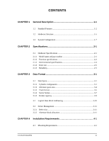
Contents Illustrations Figures Figure 1.1 FC model outer view 1-5 Figure 1.2 Disk/head configuration 1-6 Figure 1.3 Example of FC-AL system configuration 1-7 Figure 3.1 Cylinder configuration 3-2 Figure 3.2 Spare area in cell 3-5 Figure 3.3 Alternate cylinder 3-5 Figure 3.4 Track format 3-6 Figure 3.5 Track skew/cylinder skew 3-7 Figure 3.6 Sector format 3-8 Figure 3.7 Alternate block allocation by FORMAT UNIT command .........3-13 Figure 3.8 Alternate block allocation by REASSIGN BLOCKS command 3-14 Figure 4.1 External dimensions 4-2 Figure 4.2 IDD orientations 4-3 Figure 4.3 Mounting frame structure 4-4 Figure 4.4 Limitation of side-mounting 4-4 Figure 4.5 Surface temperature measurement points 4-5 Figure 4.6 Service clearance area 4-6 Figure 4.7 Current waveform (+12 VDC 4-7 Figure 4.8 AC noise filter (recommended 4-8 Figure 4.9 Connector location 4-9 Figure 4.10 SCA2 type connector 4-10 Figure 5.1 Checking the IDD connection (A 5-8 Figure 5.2 Checking the IDD connection (B 5-9 Figure 6.1 Revision label (example 6-9 Figure 6.2 Indicating revision numbers 6-10 Figure 6.3 Test flowchart 6-11 Figure 7.1 Format of extended sense data 7-2 Figure 8.1 Circuit configuration 8-4 Figure 8.2 IDD operation sequence at power-on 8-5 Figure 8.3 Block diagram of read-write circuit 8-8 Figure 8.4 Block diagram of servo control circuit 8-10 Figure 8.5 Position of servo track 8-12 Figure 8.6 Servo frame 8-12 Figure A.1 Locations of connector A-2 xvi C141-E133-02EN
-
 1
1 -
2
-
3
-
4
-
5
-
6
-
7
-
8
-
9
-
10
-
11
-
12
-
13
-
14
-
15
-
16
-
 17
17 -
 18
18 -
 19
19 -
 20
20 -
 21
21 -
 22
22 -
 23
23 -
 24
24 -
 25
25 -
 26
26 -
 27
27 -
28
-
29
-
30
-
31
-
32
-
33
-
34
-
35
-
36
-
37
-
38
-
39
-
40
-
41
-
42
-
43
-
44
-
45
-
46
-
47
-
48
-
49
-
50
-
51
-
52
-
53
-
54
-
55
-
56
-
57
-
58
-
59
-
60
-
61
-
62
-
63
-
64
-
65
-
66
-
67
-
68
-
69
-
70
-
71
-
72
-
73
-
74
-
75
-
76
-
77
-
78
-
79
-
80
-
81
-
82
-
83
-
84
-
85
-
86
-
87
-
88
-
89
-
90
-
91
-
92
-
93
-
94
-
95
-
96
-
97
-
98
-
99
-
100
-
101
-
102
-
103
-
104
-
105
-
106
-
107
-
108
-
109
-
110
-
111
-
112
-
113
-
114
-
115
-
116
-
117
-
118
-
119
-
120
-
121
-
122
-
123
-
124
-
125
-
126
-
127
-
128
-
129
-
130
-
131
-
132
-
133
-
134
-
135
-
136
-
137
-
138
-
139
-
140
-
141
-
142
-
143
-
144
-
145
-
146
-
147
-
148
 |
 |
