Fujitsu MAN3367FC Manual/User Guide - Page 32
Fujitsu MAN3367FC - Enterprise 36.7 GB Hard Drive Manual
 |
View all Fujitsu MAN3367FC manuals
Add to My Manuals
Save this manual to your list of manuals |
Page 32 highlights
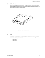
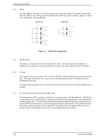
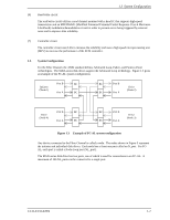
General Description (1) Loop configuration A port embedded with sending and receiving circuits uses differential signals to send and receive data on electric signal lines. A pair of signal lines is called a link. Since signals are sent in one direction on a link, the links in a system must be connected to form a loop. The FC-AL interface sends and receives data via nodes on the loop. Therefore, if a node connected to a loop is powered off or the interface signals of a node cannot be sent or received correctly, the loop does not work normally. A common solution preventing this problem from occurring is to add a port bypass circuit on the back plane of the system. BC in Figure 1.3 indicates the port bypass circuit. (2) Node addressing A specific device number called a SEL ID is assigned to each node on a Fibre Channel loop. The combination of signal levels on the back plane is used to define the SEL ID of a disk drive. The signal levels are sent on the seven signals (from SEL_0 to SEL_6) from CN1, which serves as an SCA interface connector. SEL_6 is the most significant bit (MSB), having a bit weight of the sixth power of 2, and SEL_0 is the least significant bit (LSB), having a bit weight of the zeroth power of 2. Any number from 0 (X'00) to 125 (X'7D') can be assigned as the SEL ID of a disk drive. 1-8 C141-E133-02EN
-
 1
1 -
2
-
3
-
4
-
5
-
6
-
7
-
8
-
9
-
10
-
11
-
12
-
13
-
14
-
15
-
16
-
17
-
18
-
19
-
20
-
21
-
22
-
23
-
24
-
25
-
26
-
 27
27 -
 28
28 -
 29
29 -
 30
30 -
 31
31 -
 32
32 -
 33
33 -
 34
34 -
 35
35 -
 36
36 -
 37
37 -
38
-
39
-
40
-
41
-
42
-
43
-
44
-
45
-
46
-
47
-
48
-
49
-
50
-
51
-
52
-
53
-
54
-
55
-
56
-
57
-
58
-
59
-
60
-
61
-
62
-
63
-
64
-
65
-
66
-
67
-
68
-
69
-
70
-
71
-
72
-
73
-
74
-
75
-
76
-
77
-
78
-
79
-
80
-
81
-
82
-
83
-
84
-
85
-
86
-
87
-
88
-
89
-
90
-
91
-
92
-
93
-
94
-
95
-
96
-
97
-
98
-
99
-
100
-
101
-
102
-
103
-
104
-
105
-
106
-
107
-
108
-
109
-
110
-
111
-
112
-
113
-
114
-
115
-
116
-
117
-
118
-
119
-
120
-
121
-
122
-
123
-
124
-
125
-
126
-
127
-
128
-
129
-
130
-
131
-
132
-
133
-
134
-
135
-
136
-
137
-
138
-
139
-
140
-
141
-
142
-
143
-
144
-
145
-
146
-
147
-
148
 |
 |
