Fujitsu MAN3367FC Manual/User Guide - Page 31
System Configuration
 |
View all Fujitsu MAN3367FC manuals
Add to My Manuals
Save this manual to your list of manuals |
Page 31 highlights
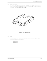
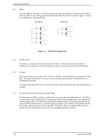
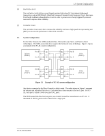
1.3 System Configuration (6) Read/write circuit The read/write circuit utilizes a read channel mounted with a head IC that supports high-speed transmission and an MEEPR4ML (Modified Enhanced Extended Partial Response Class 4 Maximum Likelihood) modulation/demodulation circuit in order to prevent errors being triggered by external noise and to improve data reliability. (7) Controller circuit The controller circuit uses LSIs to increase the reliability and uses a high speed microprocessing unit (MPU) to increase the performance of the SCSI controller. 1.3 System Configuration For the Fibre Channel, the ANSI standard defines Arbitrated Loop, Fabric, and Point-to-Point technologies. The MAN-series disk drives support the Arbitrated Loop technology. Figure 1.3 gives an example of the FC-AL system configuration. Port B BC Initiator (Node-1) Port A BC BC Port B Drive (Node-2) BC Port A Port B BC Drive (Node-4) Port A BC BC Port B Drive (Node-3) BC Port A Figure 1.3 Example of FC-AL system configuration Any device connected to the Fibre Channel is called a node. The nodes shown in Figure 3 represent the initiator and individual disk drives. Each node has at least one port called an N_port. For FCAL, each port is called a Node-Loop port (NL_port). The MAN-series disk drive has two ports, one of which is used for connections to an FC-AL. A maximum of 126 NL_ports can be connected to a single port. C141-E133-02EN 1-7
-
 1
1 -
2
-
3
-
4
-
5
-
6
-
7
-
8
-
9
-
10
-
11
-
12
-
13
-
14
-
15
-
16
-
17
-
18
-
19
-
20
-
21
-
22
-
23
-
24
-
25
-
 26
26 -
 27
27 -
 28
28 -
 29
29 -
 30
30 -
 31
31 -
 32
32 -
 33
33 -
 34
34 -
 35
35 -
 36
36 -
37
-
38
-
39
-
40
-
41
-
42
-
43
-
44
-
45
-
46
-
47
-
48
-
49
-
50
-
51
-
52
-
53
-
54
-
55
-
56
-
57
-
58
-
59
-
60
-
61
-
62
-
63
-
64
-
65
-
66
-
67
-
68
-
69
-
70
-
71
-
72
-
73
-
74
-
75
-
76
-
77
-
78
-
79
-
80
-
81
-
82
-
83
-
84
-
85
-
86
-
87
-
88
-
89
-
90
-
91
-
92
-
93
-
94
-
95
-
96
-
97
-
98
-
99
-
100
-
101
-
102
-
103
-
104
-
105
-
106
-
107
-
108
-
109
-
110
-
111
-
112
-
113
-
114
-
115
-
116
-
117
-
118
-
119
-
120
-
121
-
122
-
123
-
124
-
125
-
126
-
127
-
128
-
129
-
130
-
131
-
132
-
133
-
134
-
135
-
136
-
137
-
138
-
139
-
140
-
141
-
142
-
143
-
144
-
145
-
146
-
147
-
148
 |
 |
