Fujitsu MAN3367FC Manual/User Guide - Page 45
Spare area in cell, Alternate cylinder, Track format
 |
View all Fujitsu MAN3367FC manuals
Add to My Manuals
Save this manual to your list of manuals |
Page 45 highlights
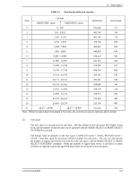
3.1 Data Space Cell Note: This drive manages alternate spare areas for each cell, which is a set of cylinders. The default value for the number of cylinders is four. Figure 3.2 Spare area in cell An alternate cylinder is used when spare sectors in a cell are used up or 0 is specified as the number of spare sectors in a cell. 1 cylinder at the end of each zone of the user space is allocated as alternate cylinders as shown in Figure 3.3. The user space and the CE space share the alternate cylinders. Zone Figure 3.3 Alternate cylinder Note: Zero cannot be specified for both the number of spare sectors in each cylinder and the number of alternate cylinders. 3.1.3 Track format (1) Physical sector allocation Figure 3.4 shows the allocation of the physical sectors in a track. The length in bytes of each physical sector and the number of sectors per track vary depending on the logical data block length. The unused area (G4) exists at the end of the track in formats with most logical data block lengths. The interval of the sector pulse (length of the physical sector) is decided by multiple of 40MHz free running frequency. This clock is not equal to the interval of the byte clock for each zone. Therefore, the physical sector length cannot be described with a byte length. C141-E133-02EN 3-5
-
 1
1 -
2
-
3
-
4
-
5
-
6
-
7
-
8
-
9
-
10
-
11
-
12
-
13
-
14
-
15
-
16
-
17
-
18
-
19
-
20
-
21
-
22
-
23
-
24
-
25
-
26
-
27
-
28
-
29
-
30
-
31
-
32
-
33
-
34
-
35
-
36
-
37
-
38
-
39
-
 40
40 -
 41
41 -
 42
42 -
 43
43 -
 44
44 -
 45
45 -
 46
46 -
 47
47 -
 48
48 -
 49
49 -
 50
50 -
51
-
52
-
53
-
54
-
55
-
56
-
57
-
58
-
59
-
60
-
61
-
62
-
63
-
64
-
65
-
66
-
67
-
68
-
69
-
70
-
71
-
72
-
73
-
74
-
75
-
76
-
77
-
78
-
79
-
80
-
81
-
82
-
83
-
84
-
85
-
86
-
87
-
88
-
89
-
90
-
91
-
92
-
93
-
94
-
95
-
96
-
97
-
98
-
99
-
100
-
101
-
102
-
103
-
104
-
105
-
106
-
107
-
108
-
109
-
110
-
111
-
112
-
113
-
114
-
115
-
116
-
117
-
118
-
119
-
120
-
121
-
122
-
123
-
124
-
125
-
126
-
127
-
128
-
129
-
130
-
131
-
132
-
133
-
134
-
135
-
136
-
137
-
138
-
139
-
140
-
141
-
142
-
143
-
144
-
145
-
146
-
147
-
148
 |
 |
