Fujitsu MAN3367FC Manual/User Guide - Page 141
START/STOP UNIT command
 |
View all Fujitsu MAN3367FC manuals
Add to My Manuals
Save this manual to your list of manuals |
Page 141 highlights
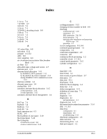
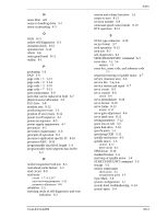
N noise filter 4-8 notes on handling drive 5-1 notes on mounting 4-3 O OGB 8-11 online self-diagnostics 6-3 operation check 6-12 operation test 6-12 others 4-6 outer guard band 8-11 outline 8-1 P packaging 5-2 PAD 3-9 page code = 1 5-13 page code = 2 5-14 page code = 3 5-10 page code = 7 5-13 parts replacement 6-8 parts that can be replaced in field 6-7 physical sector allocation 3-5 PLO Sync 3-8 position area 8-12 positioning error rate 2-5 position of servo track 8-12 power on/off sequence 4-7 power-on sequence 8-5 power supply requirement 4-7 precaution 6-5 preventive maintenance 6-6 principle of operation 8-1 processor-application specific IC 8-10 processor-ASIC 8-10 programmable data block length 1-4 programmable multi-segment data buffer 1-3 R random/sequential read test 6-5 read-ahead cache feature 1-3 read circuit 8-9 read/write circuit 1-7, 8-3, 8-7 error recovery parameter 5-13 parameter adjustment 8-6 reliability 2-5 reporting result of self-diagnostics and error indication 6-3 C141-E133-02EN Index reserve and release functions 1-3 return-to-zero 8-13 revision number 6-9 rotational speed control mode 8-13 RTZ operation 8-13 S SCA2 type connector 4-10 sector format 3-7 seek operation 8-13 seek test 6-2 self-diagnostics 6-1 SEND DIAGNOSTIC command 6-3 sense data 7-1, 7-4 analysis 7-3 sense key, sense code, and subsense code 7-1 sequential starting of spindle motor 4-7 service clearance area 4-6 service life 2-6, 6-6 service system and repair 6-7 servo circuit 8-3 servo control 8-9 circuit 8-9 servo demodulator 8-10 servo format 8-10 servo frame 8-12 format 8-12 servo gain adjustment 8-6 servo mark area 8-11 setting parameter 5-12 spare area in cell 3-5 spare disk drive 5-16 specification 2-1 specifying CDB 5-11 spindle mechanism 8-2 spindle motor 1-6 control 8-12 drive circuit 8-3 SPM driver 8-10 standard feature 1-2 start/stop of spindle motor 1-4 START/STOP UNIT command 5-6 storage 5-2 surface temperature check point 4-5 measurement point 4-5 Sync Mark 3-8 system configuration 1-7 system-level troubleshooting 6-14 system space 3-4 IN-3
-
 1
1 -
2
-
3
-
4
-
5
-
6
-
7
-
8
-
9
-
10
-
11
-
12
-
13
-
14
-
15
-
16
-
17
-
18
-
19
-
20
-
21
-
22
-
23
-
24
-
25
-
26
-
27
-
28
-
29
-
30
-
31
-
32
-
33
-
34
-
35
-
36
-
37
-
38
-
39
-
40
-
41
-
42
-
43
-
44
-
45
-
46
-
47
-
48
-
49
-
50
-
51
-
52
-
53
-
54
-
55
-
56
-
57
-
58
-
59
-
60
-
61
-
62
-
63
-
64
-
65
-
66
-
67
-
68
-
69
-
70
-
71
-
72
-
73
-
74
-
75
-
76
-
77
-
78
-
79
-
80
-
81
-
82
-
83
-
84
-
85
-
86
-
87
-
88
-
89
-
90
-
91
-
92
-
93
-
94
-
95
-
96
-
97
-
98
-
99
-
100
-
101
-
102
-
103
-
104
-
105
-
106
-
107
-
108
-
109
-
110
-
111
-
112
-
113
-
114
-
115
-
116
-
117
-
118
-
119
-
120
-
121
-
122
-
123
-
124
-
125
-
126
-
127
-
128
-
129
-
130
-
131
-
132
-
133
-
134
-
135
-
 136
136 -
 137
137 -
 138
138 -
 139
139 -
 140
140 -
 141
141 -
 142
142 -
 143
143 -
 144
144 -
 145
145 -
 146
146 -
147
-
148
 |
 |
