Fujitsu MAN3367FC Manual/User Guide - Page 20
Model Names and Product Numbers
 |
View all Fujitsu MAN3367FC manuals
Add to My Manuals
Save this manual to your list of manuals |
Page 20 highlights
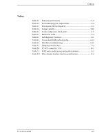
Contents 8.3 Circuit Configuration 8-3 8.4 Power-On Sequence 8-5 8.5 Factory-Calibration 8-6 8.6 Read/Write Circuit 8-7 8.6.1 Head IC 8-7 8.6.2 Write circuit 8-7 8.6.3 Read circuit 8-9 8.7 Servo Control 8-9 8.7.1 8.7.2 8.7.3 8.7.4 8.7.5 Servo control circuit 8-9 Servo format 8-10 Servo frame format 8-12 Spindle motor control 8-12 Voice coil motor control 8-13 APPENDIX A Locations of Connector A-1 A.1 Locations of Connector A-2 APPENDIX B Connector Signal Allocation B-1 B.1 Interface (FC-SCA) Connector Signal Allocation B-2 APPENDIX C Model Names and Product Numbers C-1 C.1 Model Names and Product Numbers C-2 APPENDIX D Fibre Channel Interface Functions D-1 D.1 Fibre Channel Interface Function Specifications D-2 xiv C141-E133-02EN
-
 1
1 -
2
-
3
-
4
-
5
-
6
-
7
-
8
-
9
-
10
-
11
-
12
-
13
-
14
-
 15
15 -
 16
16 -
 17
17 -
 18
18 -
 19
19 -
 20
20 -
 21
21 -
 22
22 -
 23
23 -
 24
24 -
 25
25 -
26
-
27
-
28
-
29
-
30
-
31
-
32
-
33
-
34
-
35
-
36
-
37
-
38
-
39
-
40
-
41
-
42
-
43
-
44
-
45
-
46
-
47
-
48
-
49
-
50
-
51
-
52
-
53
-
54
-
55
-
56
-
57
-
58
-
59
-
60
-
61
-
62
-
63
-
64
-
65
-
66
-
67
-
68
-
69
-
70
-
71
-
72
-
73
-
74
-
75
-
76
-
77
-
78
-
79
-
80
-
81
-
82
-
83
-
84
-
85
-
86
-
87
-
88
-
89
-
90
-
91
-
92
-
93
-
94
-
95
-
96
-
97
-
98
-
99
-
100
-
101
-
102
-
103
-
104
-
105
-
106
-
107
-
108
-
109
-
110
-
111
-
112
-
113
-
114
-
115
-
116
-
117
-
118
-
119
-
120
-
121
-
122
-
123
-
124
-
125
-
126
-
127
-
128
-
129
-
130
-
131
-
132
-
133
-
134
-
135
-
136
-
137
-
138
-
139
-
140
-
141
-
142
-
143
-
144
-
145
-
146
-
147
-
148
 |
 |

Contents
xiv
C141-E133-02EN
8.3
Circuit Configuration
...............................................................................
8-3
8.4
Power-On Sequence
.................................................................................
8-5
8.5
Factory-Calibration
..................................................................................
8-6
8.6
Read/Write Circuit
...................................................................................
8-7
8.6.1
Head IC
..................................................................................................
8-7
8.6.2
Write circuit
...........................................................................................
8-7
8.6.3
Read circuit
............................................................................................
8-9
8.7
Servo Control
...........................................................................................
8-9
8.7.1
Servo control circuit
..............................................................................
8-9
8.7.2
Servo format
........................................................................................
8-10
8.7.3
Servo frame format
..............................................................................
8-12
8.7.4
Spindle motor control
..........................................................................
8-12
8.7.5
Voice coil motor control
.....................................................................
8-13
APPENDIX A
Locations of Connector
...........................................................
A-1
A.1
Locations of Connector
..........................................................................
A-2
APPENDIX B
Connector Signal Allocation
....................................................
B-1
B.1
Interface (FC-SCA) Connector Signal Allocation
..................................
B-2
APPENDIX C
Model Names and Product Numbers
......................................
C-1
C.1
Model Names and Product Numbers
......................................................
C-2
APPENDIX D
Fibre Channel Interface Functions
..........................................
D-1
D.1
Fibre Channel Interface Function Specifications
...................................
D-2