HP 17-p000 17-p199 - Maintenance and Service Guide - Page 20
Bottom
 |
View all HP 17-p000 manuals
Add to My Manuals
Save this manual to your list of manuals |
Page 20 highlights
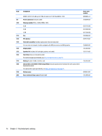
Bottom Component (1) Battery lock (2) Battery bay (3) Vents (6) (4) Battery release latch Description Locks the battery in the battery bay. Holds the battery. Enable airflow to cool internal components. NOTE: The computer fan starts up automatically to cool internal components and prevent overheating. It is normal for the internal fan to cycle on and off during routine operation. Releases the battery. 12 Chapter 2 External component identification
-
 1
1 -
2
-
3
-
4
-
5
-
6
-
7
-
8
-
9
-
10
-
11
-
12
-
13
-
14
-
 15
15 -
 16
16 -
 17
17 -
 18
18 -
 19
19 -
 20
20 -
 21
21 -
 22
22 -
 23
23 -
 24
24 -
 25
25 -
26
-
27
-
28
-
29
-
30
-
31
-
32
-
33
-
34
-
35
-
36
-
37
-
38
-
39
-
40
-
41
-
42
-
43
-
44
-
45
-
46
-
47
-
48
-
49
-
50
-
51
-
52
-
53
-
54
-
55
-
56
-
57
-
58
-
59
-
60
-
61
-
62
-
63
-
64
-
65
-
66
-
67
-
68
-
69
-
70
-
71
-
72
-
73
-
74
-
75
-
76
-
77
-
78
-
79
-
80
-
81
-
82
-
83
-
84
-
85
-
86
-
87
-
88
-
89
-
90
-
91
-
92
-
93
-
94
-
95
-
96
-
97
-
98
-
99
-
100
-
101
-
102
-
103
-
104
-
105
-
106
 |
 |

Bottom
Component
Description
(1)
Battery lock
Locks the battery in the battery bay.
(2)
Battery bay
Holds the battery.
(3)
Vents (6)
Enable airflow to cool internal components.
NOTE:
The computer fan starts up automatically to cool
internal components and prevent overheating. It is normal
for the internal fan to cycle on and off during routine
operation.
(4)
Battery release latch
Releases the battery.
12
Chapter 2
External component identification